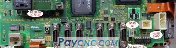
Fanuc analog spindle output often has SP1241 alarms. The note in the official manual is: the D/A converter for analog spindle is abnormal. The analog spindle interface is on the FANUC system motherboard, and the OID system is as shown below:
Interface JA40 is an analog spindle output and high-speed jump output interface.
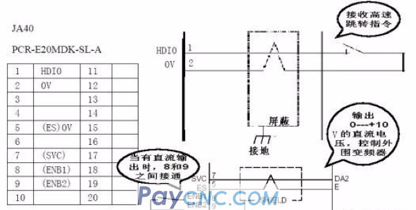
Figure SVC signal is an analog voltage output signal (0-10V), and the dashed SHIELD is a shielded line to prevent interference.
Failure case one:
Trouble phenomenon: SP1241 alarms often appear during the system debugging;
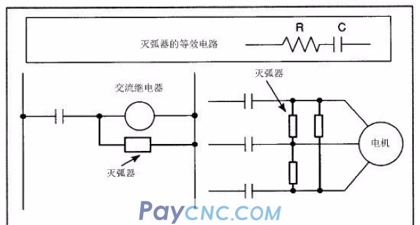
Solution: Observing the electrical cabinet, it is found that SP1241 alarm is prone to occur when the solenoid valve is closed, and the three-phase power supply is not equipped with an arc extinguisher. It is suspected that it will produce electromagnetic interference during operation, which causes the system to mistakenly think that the analog voltage is abnormal and generate SP1241 alarm. Disconnect it (AC contactor) to make the system run. After the machine tool has been working for half a day, no SP1241 alarm occurs. The three-phase arc extinguisher is added to the AC contactor, and the system runs for half a day without SP1241 alarm.
Question keywords: arc extinguishing, interference;
Remarks: The user has not responded and this alarm reappears;
Principle analysis: The working principle of the arc extinguisher is to make it change smoothly when encountering a large current, so as to avoid interference and protect electronic components;
Failure case two:
Trouble phenomenon: SP1241 alarm occasionally occurs during the use of the system: mainly occurs during the simulation of spindle speed changes;
Solution: After adjusting the inverter's PWM from 15K to 1K, the alarm will be eliminated;
Question keywords: PWM (inverter carrier frequency);
Remarks: After a telephone return visit: the frequency of the alarm is low before adjusting the inverter's PWM parameters: it occurs once in several days; after adjusting the inverter's PWM parameters, the alarm phenomenon still exists, but the frequency is very low;
Principle analysis: The inverter controls the motor acceleration and deceleration accuracy through PWM. The greater the value, the greater the control accuracy, and the greater the impact on the 5 and 7 pins of JA40 when the spindle speed changes --- the analysis is problematic (should be: The higher the frequency, the higher the frequency of the interference source, the more susceptible to interference).
Failure case three:
Trouble phenomenon: SP1241 alarms often appear during the use of the system: basically every time it is turned on;
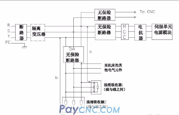
Solution: Observe the electric cabinet and find that the analog voltage output cable is hung on the electric cabinet transformer, and connect to the inverter through the terminal block;
Solution: Use shielded wire to connect JA40 pin 5/7 directly to the inverter (without passing through the terminal block), and keep a certain distance from the transformer;
Question keywords: transformer, transfer terminal block, interference;
Remarks: The user has used it continuously for nearly 2 weeks and the alarm did not appear again;
Principle analysis: A. As we all know, the transformer is used for voltage conversion by coil induction, so the transformer is a huge source of interference. Any cable close to the transformer will be induced to get electricity; and the line drawn from the 5th and 7th pins of JA40 Cables that are too close to the transformer will be energized and cause system alarms; B. The middle terminal block will introduce interference from many other circuits (when dealing with the frequent damage of the JA6 port of the laser analog interface board in Jinan Jiemai factory, it can be clearly found by using the oscilloscope The transfer terminal block introduces a lot of interference), which should also be avoided;
Failure case four:
Trouble phenomenon: SP1241 alarms often occur during the system use: the frequency of occurrence is not fixed: sometimes once a day, sometimes once a week; the occurrence time is not fixed, sometimes during the day, sometimes at night, not during the spindle acceleration and deceleration;
Solution: Observe the electrical cabinet and find that the transformer has a greater impact on the overall electrical cabinet;
Solution: i. Use ordinary shielded wires to connect the 5th and 7th pins of JA40 (Wuhan Office Zhao Gang changed to twisted pair and the interference increased and frequent alarms), and added 3 arc extinguishing items to the three inputs of the inverter and the head frame input Move the transformer away from the system (the original position is directly below the system, and the new position is about 70cm away from the system);
Question keywords: transformer, interference;
Failure case five:
Trouble phenomenon: SP1241 alarms often appear during the use of the system: the frequency of occurrence is about 3-4 times a day: sometimes it is 8 or 9 in the morning, sometimes 3 or 4 in the morning; when the alarm occurs, it is during the tool change process of the turret Or the moment the tool is changed;
Solution: Observing the electrical cabinet and discovering that: except for the 220V single-phase AC coil of the turret, there is no arc extinguisher installed, the other three and single-phase contactors have been installed with arc extinguishers when they leave the factory in Yunnan CY;
Solution: add 220V single-phase AC coil corresponding to the turret (forward and reverse)
Failure case six:
Fault phenomenon: SP1241 alarm occurs as soon as the system is powered on during the debugging process;
Solution: power on the system alone, no SP1241 alarm; power on together with Mitsubishi servo drive, immediately SP1241 alarm; turn off Mitsubishi servo starter, power on other parts of the electrical cabinet, no SP1241 alarm;
Problem keywords: interference;
Remarks: On March 28, an oscilloscope was used to confirm that its fluctuation range exceeded plus or minus 20V;
Principle analysis: It is related to the internal structure of the Mitsubishi drive. Because there is no special equipment such as oscilloscope on site, it is impossible to accurately determine the degree of interference (later confirmed that the interference amplitude is above 40V), but it has been confirmed to be related to the Mitsubishi servo drive.
Failure case seven:
Trouble phenomenon: SP1241 alarm occurs as soon as the system is turned on during the debugging process;
Solution: After contacting the maintenance department for confirmation, the system was tested and it was a hardware failure. After replacing the system motherboard, the alarm was eliminated.
Problem keywords: hardware failure;
Note: A bad system motherboard may also cause this fault.
Summary: FANUC analog spindle SP1241 alarms, either the system motherboard is broken, or it is caused by external interference.
In FANUC 0iC system, some are serial spindles (driving the spindle drives produced by FANUC) and some are analog spindles. How to distinguish it from the main board?
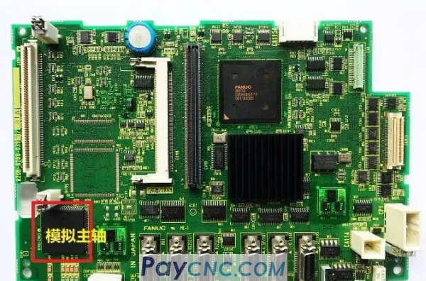
The picture above is an OIC motherboard. There is a square chip in the lower left corner. If soldered, it has an analog spindle. If it is not soldered, it is a serial spindle motherboard.
|
 |
| Products Catalogue | Home | About Us | Retrofit | Download | News | Tech Support | Contact Us | |
|
|
|