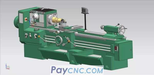
Why is it called CA6140?
C stands for lathe,
A is the structural feature code to distinguish C6140, which can be understood as an upgraded model.
6 stands for horizontal,
1 represents the basic type,
40 represents the maximum rotation diameter.
For the specific structure, take a look at the hand drawing
1. Outer body of machine tool
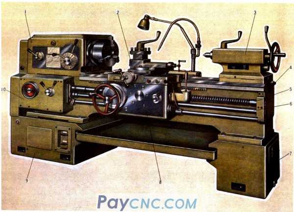
The names of each component indicated by the numbers in the figure are as follows:
1. Spindle box, 2. Tool post parts 3. Tailstock 4. Bed 5. Lead screw 6. Smooth bar 7. Right leg 8. Slide box 9. Left leg 10. Feed box
CA6140 Ordinary Lathe is a universal machine tool with ordinary precision. It is suitable for machining internal and external rotating surfaces on various shafts, sleeves and disc parts, as well as turning end faces.
Threading, drilling, reaming, knurling, etc. can all be processed. Of course, as we said before, it can be modified for non-turning processing.
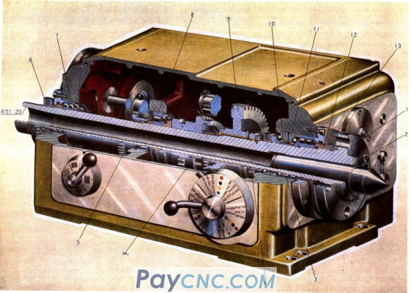
2. Spindle drive
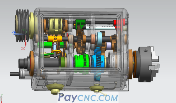 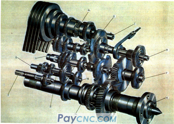
M1 is a two-way multi-plate friction clutch that can rotate the main shaft forward, reverse and stop, and M2 is a gear clutch
The function of the spindle drive system is to transmit the motion of the power source (motor) to the spindle, so that the spindle drives the workpiece to realize the main rotation movement, and the spindle can be changed and reversed
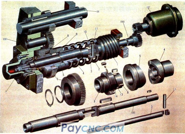
3. Assembly drawing of spindle assembly
 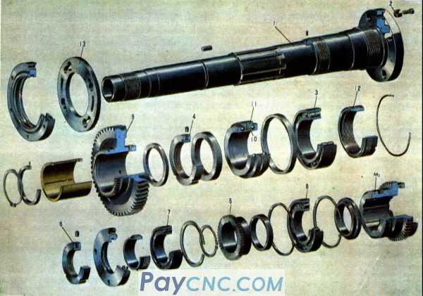
1. Spindle 2. Round block 3. Tapered hole double row radial short cylindrical roller bearing 4. Round nut 5. Straight tooth cylindrical gear 7. Tapered hole double row radial short cylindrical roller bearing 8. Single row radial Short cylindrical roller bearing 9. Helical cylindrical gear 11. Double row radial thrust ball bearing, M2 gear clutch
4. The connection structure diagram of the spindle end and the chuck
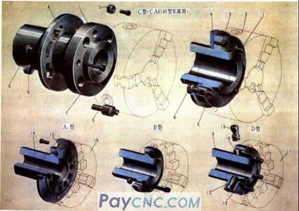
1. Spindle 2. Chuck 3. Transmission key 4. Rotating pad 5. Bolt 6. Nut 8. Positioning sleeve 15. Flange 16. Chuck, A1, A2, B, C, D flange type spindle end Different forms of connection between parts and accessories
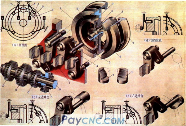
5. Friction clutch and control mechanism diagram
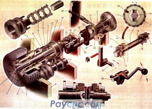
1. Control handle 8. Positioning plate 9. External friction plate 12. Sliding sleeve 15. Pull rod 16. Slip ring 14.7 Idler gear 18. Lever 19. Brake disc 20. Screw 26. Joystick 25. Connecting rod 23. Sector Gear 24. Rack shaft, I shaft, the upper left is a separate axonometric drawing
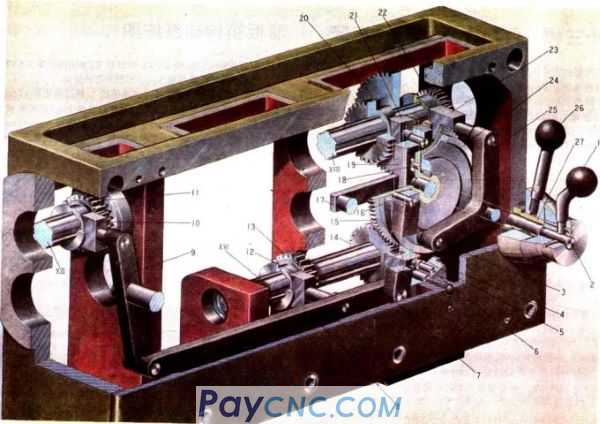
6. Spindle speed control mechanism
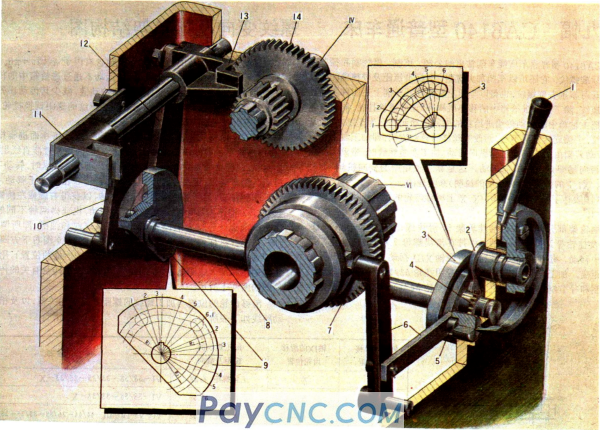
1. Handle 2. Chain 3. Reading plate 4. Chain 5. Shaft 6. Cam 7. Crank 8. Gear 9. Pull fork 10. Lever 11. III, IV axis
Handle, sector gears, 9 cams, cylindrical gears, 6, 10, 12 levers, 14 sliding gears, shafts, 13 forks, IV, vI spindles
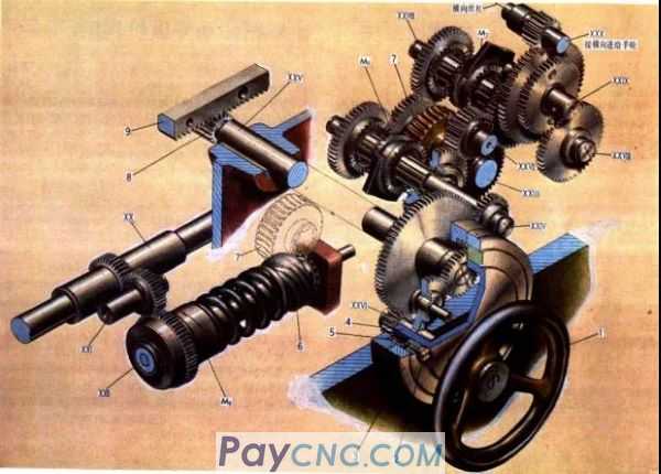
7. Thread change and hanging wheel frame structure diagram
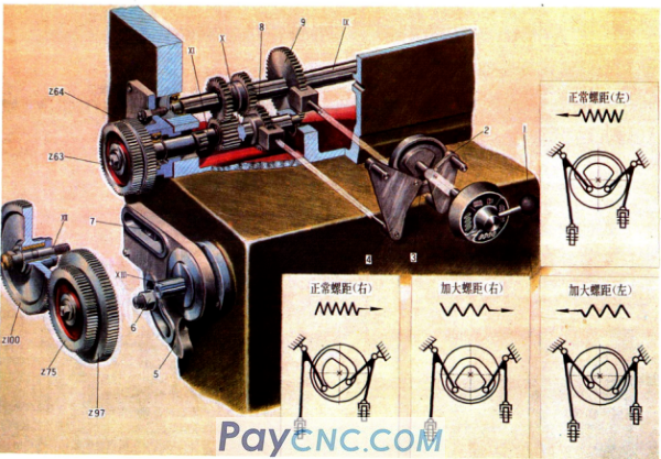
Handle, 4 levers, disc cam, hanging wheel frame, nut, slider nut, 9 sliding gear X, XII, XIII shaft
8. Feed box transmission system diagram
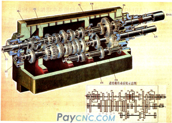
M3.M4 clutch, XVI shaft, 36 gear pairs, slip gear
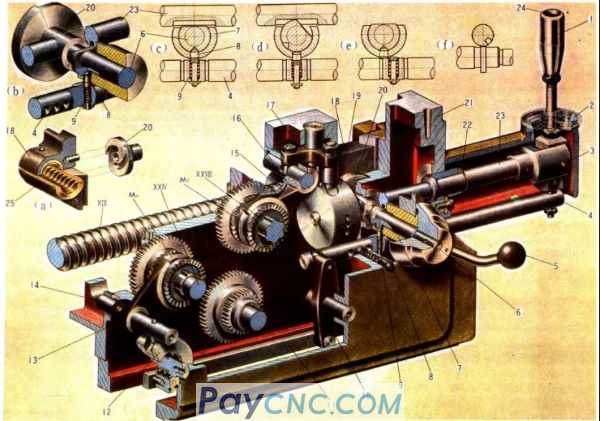
9. The basic group control mechanism diagram of the feed box
The principle diagram of the operating mechanism, c, d lever and pull block are in three positions, E ring groove
Handwheel, screw, cylindrical pin, pull block, bevel round press block, steel ball
10. The driving mechanism diagram of the feed box
Handle shaft, pull fork, 18 eccentric pin, guide rod, sliding plate, double sliding gear, pull block, disc cam
I, II, III, IV change the speed ratio of multiple groups, V is directly connected to the lead screw
11. Diagram of slide box transmission system
Screw, dial, dial body, worm, turbine, XXI, XXI, X axis, M8 safety clutch, XXX screw
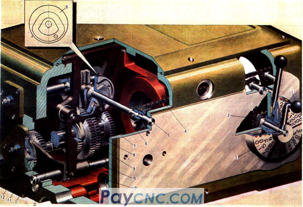
12. Box drive operating mechanism diagram
Handle, cover, round pin, handle, shaft, curve groove plate, upper half nut, slide box, shaft, snap ring, lever, push rod, cam, fork, cam, lever, fork, fixed sleeve
The curve groove type on the curve groove plate, the operating handle of the opening and closing nut, the working principle of the def interlocking mechanism
XIX screw, M6 dog clutch, XXVII shaft, M7. dog clutch, M6 dog clutch
13. Safety and overrunning clutch structure diagram
Spring, tie rod, right adapter, left adapter, gear, nut, roller, star, thrust sleeve, cylindrical pin, fast motor, ejector pin, spring
XX polished rod, XXII worm shaft
14. Structure drawing of bed saddle and horizontal carriage
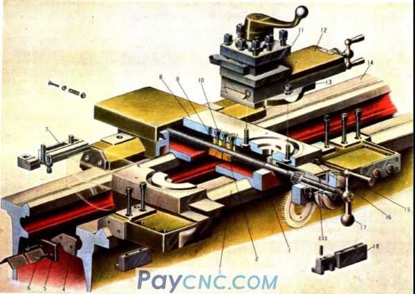
Horizontal support plate, 9 nuts, 14 tool holder guide rails, scraper, steel plate, screws, rear pressure plate, turntable (transverse support plate), model block, square tool holder, small carriage, turntable, adjusting screw, trim strip, handle, Front pressure plate, XXX screw
15. Tool holder structure diagram
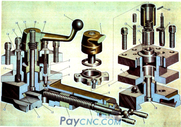
Handle, end cam, positioning pin, tool holder body, pin, small carriage, handle, lead screw, nut, turntable, insert, steel ball, spring, sleeve, sleeve, spring, threaded shaft, cylindrical pin
16. Tailstock structure diagram
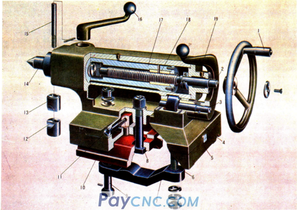
Handwheel, screw, eccentric shaft, tailstock, tailstock seat, tie rod, lever, screw, make pressure plate, adjusting screw, upper sleeve, lower sleeve, rear center, screw, handle, tailstock sleeve, nut, handle
17. Bed structure diagram
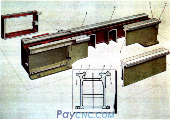
4 guide rails for tool holder parts, 3 tailstock guide rails
|
 |
| Products Catalogue | Home | About Us | Retrofit | Download | News | Tech Support | Contact Us | |
|
|
|