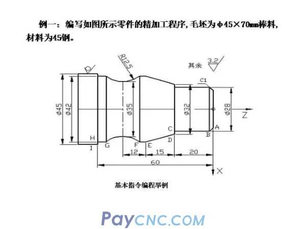
FANUC programming issues
1. Determination of the workpiece coordinate system: The origin of the CNC lathe program is usually set on the right end surface of the processed workpiece after finishing.
2. When programming the CNC lathe, it can be programmed either in absolute coordinates (using x, z), relative coordinates (using U, W), or mixed coordinates (X, W or U, Z).
3. When programming the CNC lathe, the programming in the X direction is divided into diameter programming and radius programming.
4. Determination of the way of advance and retreat: When entering the tool, the rapid path is used to approach the starting point of the workpiece. The starting point of the cutting is determined based on the principle that the tool tip does not collide with the workpiece when the tool quickly reaches this point.
FANUC commonly used commands and applications
1. Quick point positioning G00
Command format: G00X(U)Z(W)
Command function: Specify the tool post to quickly move from the current point of the tool post to the target point at the speed set by the machine tool system parameters.
Among them, X and Z are the target position values in absolute value programming, and U and W are the incremental values in X and Z directions in incremental value programming mode.

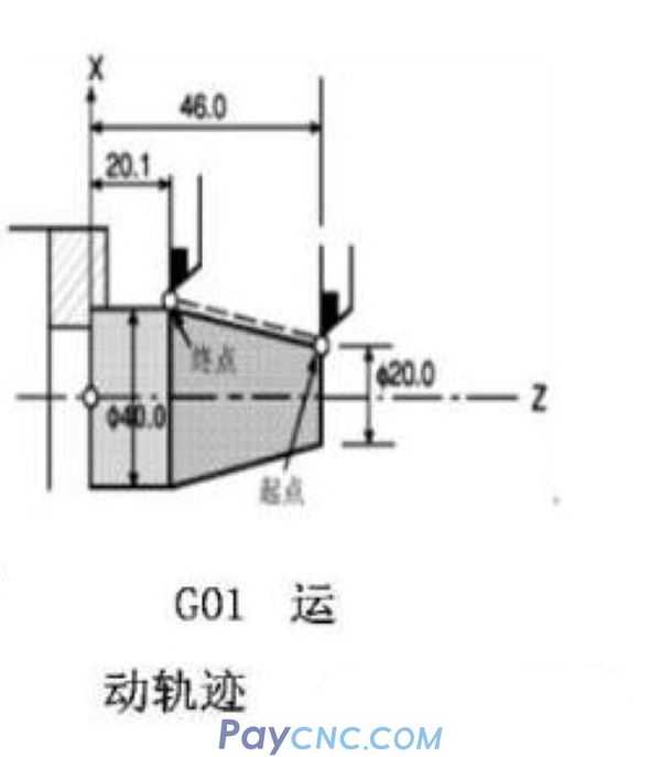
2. Linear interpolation G01
Command format: G01X(U)Z(W)F
Command function: Command the tool or workpiece to move to the specified position at the given feed speed in linear interpolation mode, and the tool will cut during the feed.
Among them: X, Z are the coordinate values of the target point, and F is the feed rate.
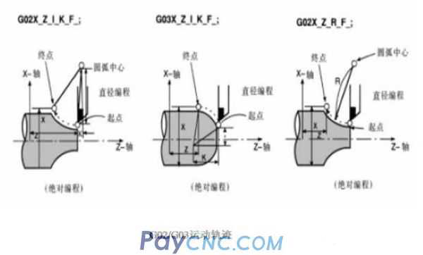
3. Circular interpolation command (G02, G03)
Command format: G02 G03 X(U)Z(W) R_____ I______ K______ F
Command function: G02 is clockwise circular interpolation, G03 is counterclockwise circular interpolation. Command the tool or workpiece to perform circular interpolation in the clockwise (or counterclockwise) direction at the given feed rate.
note:
1. X and Z are the coordinates of the end point of the arc.
2. R is the arc radius. The radius R of the arc smaller than 180° takes a positive value, and the radius R of the arc larger than 180° takes a negative value. The entire circle cannot be programmed with the arc radius R, but can only be programmed with the circle center coordinates I and K.
3. I and K respectively represent the increment of the distance between the starting point of the arc and the center of the arc in the X and Z coordinate directions. Their direction is from the starting point of the arc to the center of the circle. When the direction of I and K is the same as the coordinate, the positive value is taken, otherwise, the negative value is taken.
4. Pause instruction G04
Command format: G04X___G04U____G04 P___
Command function: When used for machining such as boring holes, turning grooves, and turning stepped shafts, the tool is required to realize no-feed smoothing in a short time.
Among them, the value after X and U is the pause time in seconds. The value MS after P cannot have decimals. This command is a non-modal command. Such as: G04 X5 G04 P2000
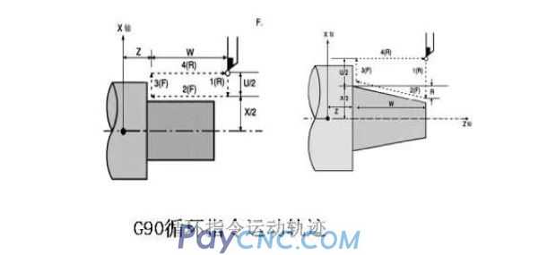
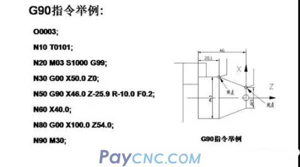
5. Simple cycle command G90 for turning inner and outer cylinder/cone
Command format: G90 X (U) Z (W) R F
Among them, X, Z, U, W, R (radius difference) are the same as G92, F specifies the feedrate
 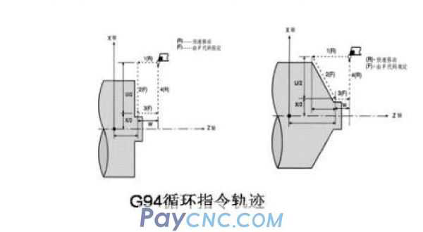
6. Cutting end face/cone simple cycle G94
Command format: G94 X(U) Z(W) R F
Among them, X, Z, U, W, R are the same as 92, F specifies the feedrate
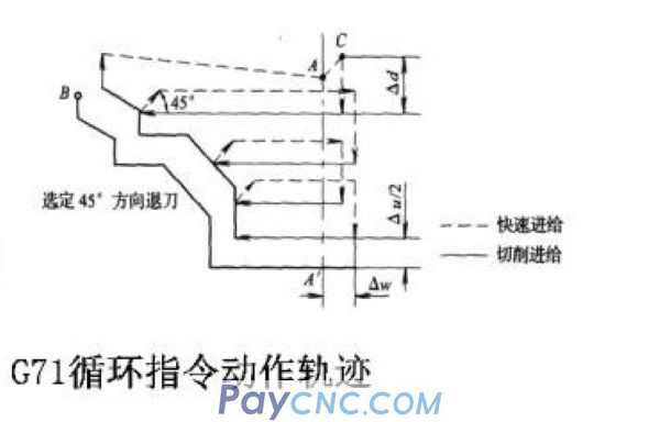
7. External rough turning compound cycle command G71
Instruction format: G71 U (Ad) R (e)
G71 P(ns)Q(nf) U(Au)W(Aw)F(f)
Instruction description: ns is the first block number of the finishing program group: nf is the last block number of the finishing program group: Ad is the depth of cut per roughing (radius value programming): e is the tool retraction amount: Au Is the finishing allowance in the x-axis direction (diameter value): Aw is the finishing allowance in the z-axis direction.
Note: 71 cycle command movement track
1. Specify the tool path between A and A in the block containing G00 or G01 with a serial number of ns, and the movement along the Z axis cannot be specified in this segment, and the tool movement command must be perpendicular to the Z axis direction.
2. The tool path from A to B must increase or decrease monotonously on the X and Z axes.
3. The program segment between P(ns) and (nf) cannot call subroutine
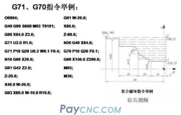
8. Finishing cycle command G70
Command format: G71 P(ns) Q(nf)
Command function: used for finishing cycle after G71, G72, G73 roughing cycle command
Note 1. F, S, T in the process of finishing turning are specified between P (ns) and Q (nf)
2. The program segment between P(ns) and Q(nf) cannot call subroutine
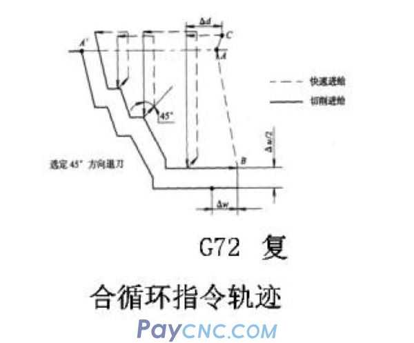
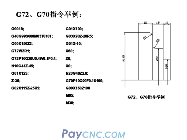
9. End face rough turning compound cycle command G72
Command format: G72 W(Ad) R(Ae)
G72 P(ns)Q(nf) U(Au) W(Aw) F(f)
Instruction description: It is suitable for rough turning of the end face of cylindrical blanks. The execution process is the same as the G71 instruction except that the turning is parallel to the X axis. Ad is the depth of cut in the Z-axis direction.
Note: closed loop command track
1. Specify the tool path between A and A in the block containing G00 or G01 with the serial number of ns, and the movement along the X axis cannot be specified in this segment. The tool movement command must be perpendicular to the X axis.
2. The tool path from A to B must increase or decrease monotonously on the X and Z axes.
3. The program segment between P(ns) and Q(nf) cannot call subroutine
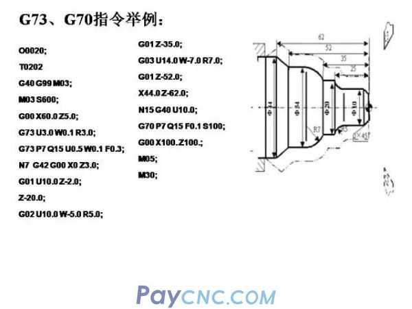
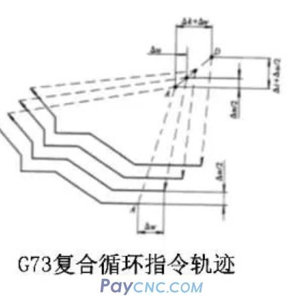
10. Fixed shape cutting compound cycle command G73
G73 has the same function as G71 and G72, but its tool path is carried out according to the finishing contour of the workpiece. It is suitable for rough machining of rough rough which is basically close to the contour of the part, such as rough turning of casting and forging rough parts.
Instruction format:
G73U (Ai) W(Ak) R
G73 P(ns) Q(nf) U(Au) F(f)
i represents the exit distance and direction along the X axis; k represents the exit distance and direction along the Z axis; R specifies the number of rough machining
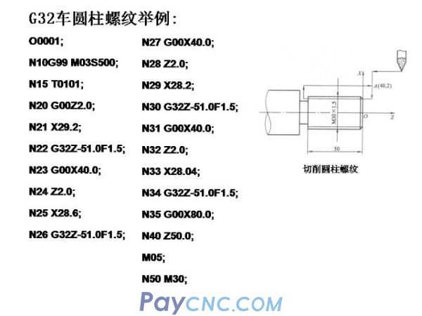
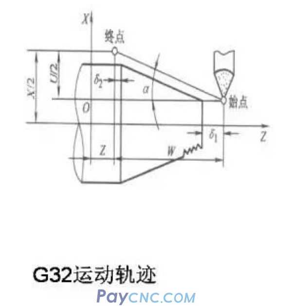
11. Thread turning designation G32
Specified format: G32 X(U)Z(w) F
Command function: turning cylindrical and conical threads. X and Z are the end position values during absolute programming: U and W are the incremental values in the X and Z directions during incremental programming: F is the thread lead value.
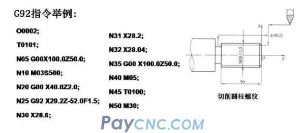 
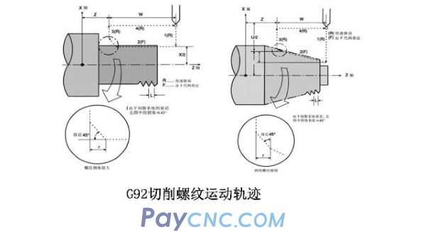
12. Thread turning cycle command G92
The thread turning cycle command regards the four actions of "cutting in a thread cutting-retreating-returning" as a cycle, and is commanded by one block.
Command format: G92 X(U) Z(W) R F
Among them, X (U), Z (W) are the end value of thread cutting: R is the radius difference between the starting point of thread cutting and the end of cutting; F is the thread lead value.
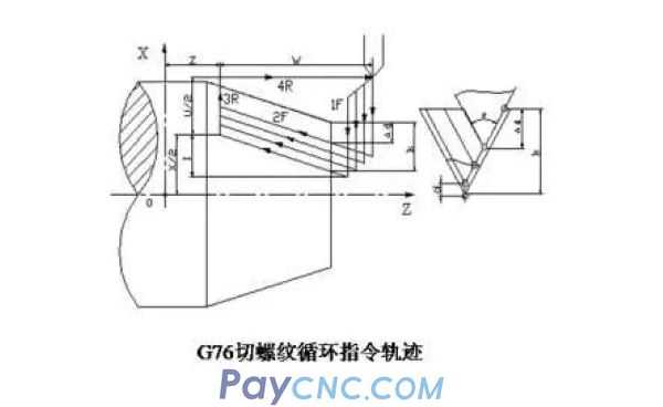
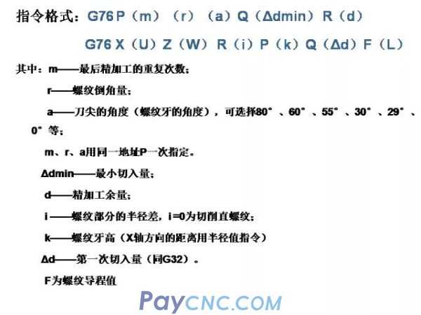
13. Compound thread cutting cycle command G76
It can complete all machining tasks of a thread segment, and its feed method is beneficial to improve the cutting conditions of the tool
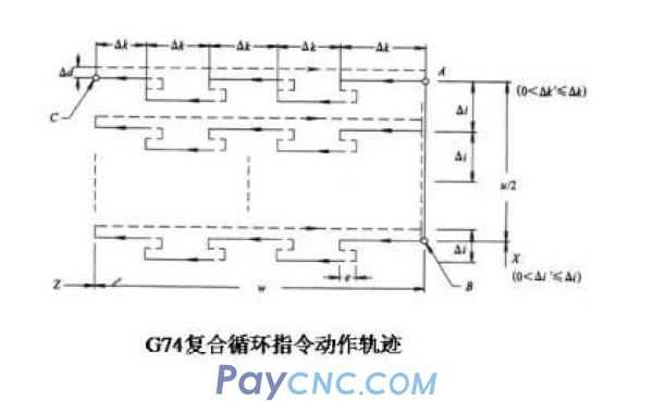 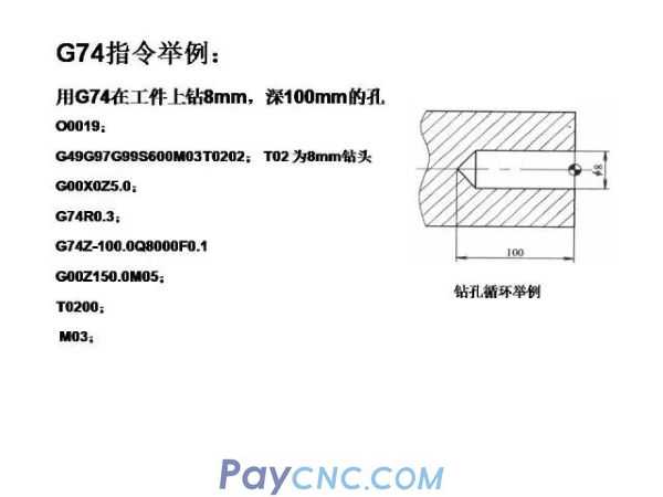 
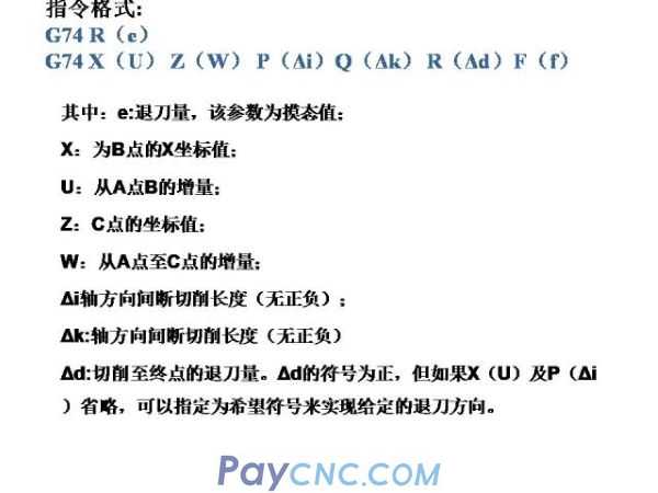
14. Deep hole drilling compound cycle command G74
The command motion track is shown in the figure, and chip breaking can be handled in the cycle. If X(U)P(Ai) and (Ad) are omitted, the result will only be operated on the Z axis for drilling
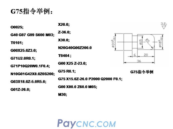  
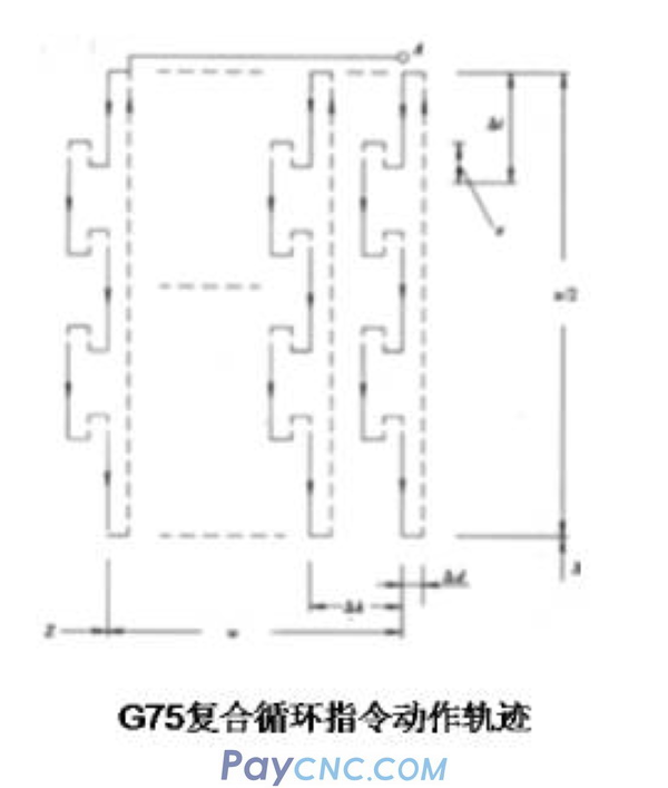
15. External and internal grooving cycle command G75
The command movement track is shown in the figure, which can be used for groove and cutting processing.
Instruction format:
G75R(e)
G75X(U)Z(W)P(Ai)Q(Ak)R(Ad)F(f)
The meaning of each parameter is the same as G74
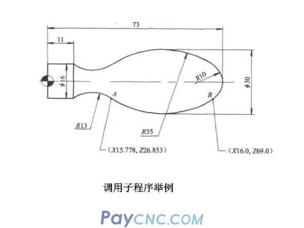
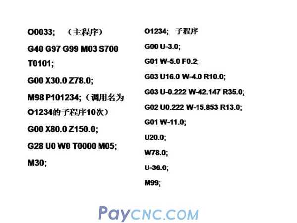
16. Call subroutine
In the process of part processing, when a certain processing content appears repeatedly, compile the repeated processing content as a subroutine, and complete the processing by calling the subroutine, which can greatly simplify the program. Instruction format: M98 P; subroutine call M99; subroutine return
Among them: P can specify 8 digits, the first four digits are the number of subroutine calls, and the last four digits indicate the program number
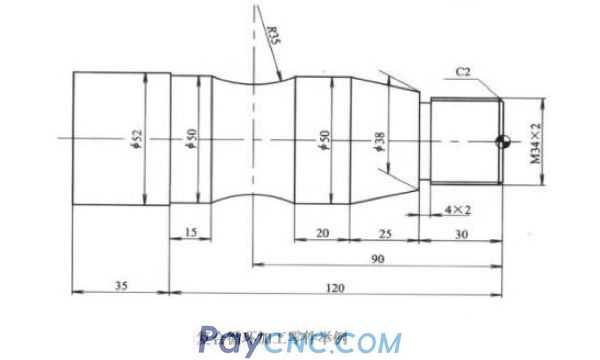
Example 2: Machining the parts shown in the figure below, the workpiece material is 45# steel, the blank size is 52, and the roughness Ra is 1.6um. Write parts processing program
Set the workpiece coordinate system as shown in the figure. The process route is: rough turning outer circle-fine turning outer circle-grooving-threading-concave round turning
Use YT15 external turning tool T01, thread and concave cutting tool T03, high-speed steel grooving tool T02, tool width 4mm
   |
 |
| Products Catalogue | Home | About Us | Retrofit | Download | News | Tech Support | Contact Us | |
|
|
|