Many people feel that manual programming of CNC lathes is cumbersome when encountering arcs, chamfering, and calculating point coordinates.
Today's article shares two knowledge points, which will save you worry and effort in programming.
1, the drawing mark of the chamfer
2. Direct drawing programming method
One, the drawing mark of the chamfer
1. When chamfering two surfaces that are inclined to each other, especially when rounding, the size of this part is very confusing. Therefore, in order to clarify the size of this part, in general, the drawing is marked from the intersection of the chamfer.
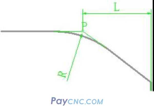
For example, in the sketch above, the rounded corners on both sides are marked with the intersection point P of the extension lines on both sides as the reference.
When programming, if G02/G03 is used, it is necessary to calculate the arc start and end coordinates.
However, when the drawings are marked, most of them are marked at the intersection of the chamfers. This is why it is cumbersome to count the points manually when the car number master encounters an arc.
2, 45-degree chamfer marking, generally indicated by the letter C (the first letter of English chamfer), such as the following figure: C3
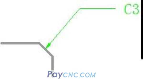
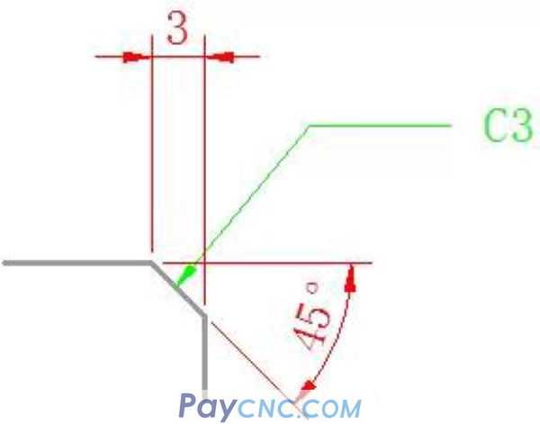
This meaning is: the slope of the chamfer is 45 degrees and the length is 3mm. It should be noted that this length is not the length of the hypotenuse. As shown below:
Second, direct drawing programming method.
As the name implies, it is programmed according to the dimensions marked on the drawing.
The format is as follows:
G01X _Z_R_ (arc)
G01X _Z_A_ (chamfer)
That is to add A or R directly after the G01 command.
Among them: A is chamfering, R is rounding.
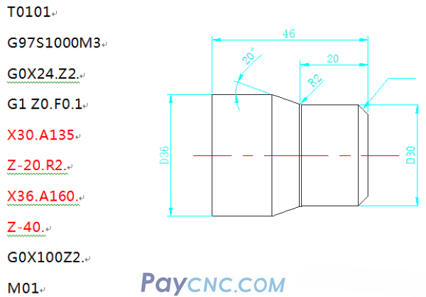
For example, the following diagram:
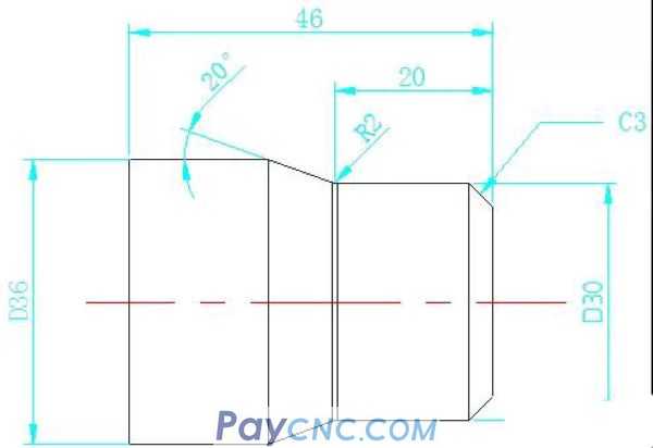
T0101
G97S1000M3
G0X24.Z2.
G1 Z0.F0.1
X30.A-45.
Z-20.R2.
X36.A-20.
Z-40.
G0X100Z2.
M01
The chamfering angle number behind A is the angle between the chamfering edge and the Z axis.
For example, the following diagram:

The angle between the chamfered edge and the Z axis, if you look at the above picture carefully, there will be two values for the angle.
For example, the chamfer of C3:
135° with the positive direction of Z axis
45° with the negative direction of Z axis
For example, the 20 degree chamfer in the picture above:
160° with the positive direction of Z axis
20° with the negative direction of Z axis
In the above programming, the included angle with the negative direction of the Z axis is selected, so the back of A is negative.
Of course, you can also choose the angle with the positive direction of the Z axis, then the following procedure is completely equivalent to the above procedure:
Based on the above analysis, we look at the program in the following diagram:
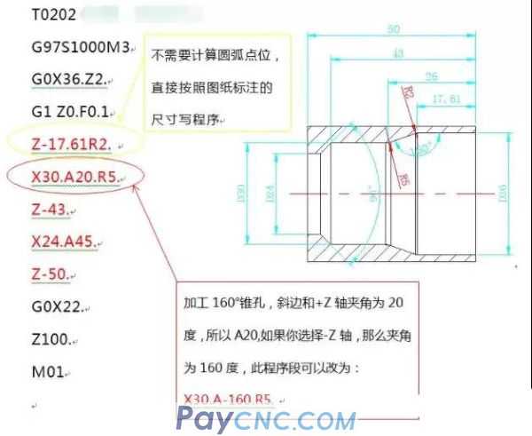
Remarks:
When using direct drawing programming, some machine tools need to add a "comma" in front of A or R. such as:
G01X24. ,A45.
G01 X30. ,A20. ,R5.
Of course, you can find system parameter #3405
Set the fourth CCR to 1, so there is no need to add a "comma" before the letters A and R.
Two cases of finishing procedures are shared above.
You may ask how to write a rough machining program. Now that you have a finishing program, you can cooperate with the cycle command you have mastered, such as G71, and you can also use the macro program to complete the program editing.
|
 |
| Products Catalogue | Home | About Us | Retrofit | Download | News | Tech Support | Contact Us | |
|
|
|