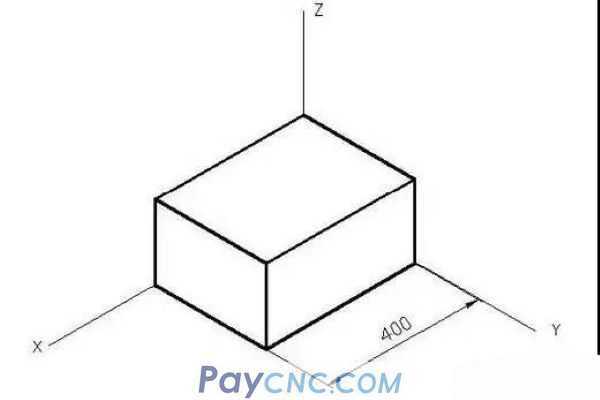
The axonometric drawing has a strong sense of three-dimensionality and good intuitiveness, but after all, the axonometric drawing is still a two-dimensional drawing, not a real three-dimensional entity, so if its dimensioning is carried out according to the general annotations, its three-dimensional effect will not be reflected, and many people will mark it. Irregularities, marking errors and correct marking methods are as follows:
1. Wrong annotation:
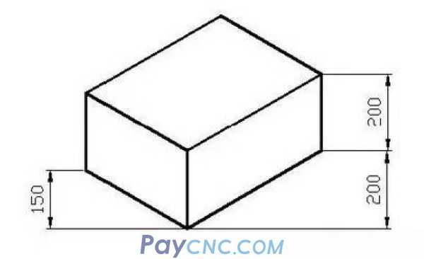
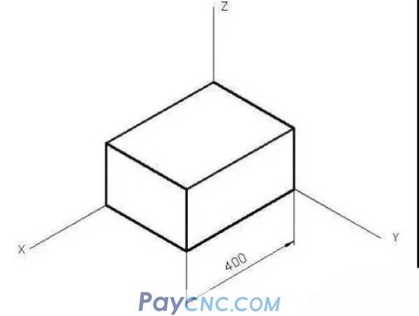
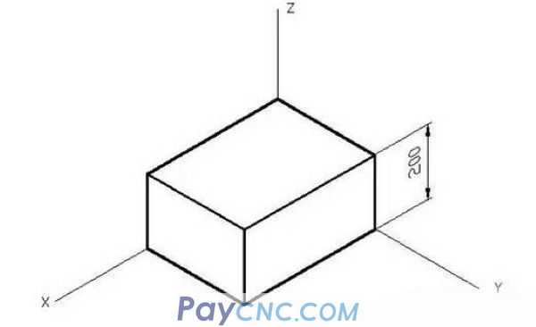
This is marked with "linear", which is obviously wrong.
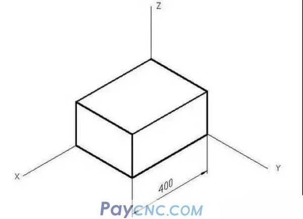
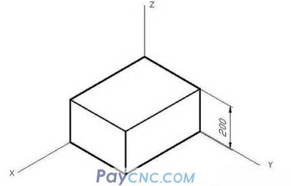
This is marked with "alignment", which is not correct.
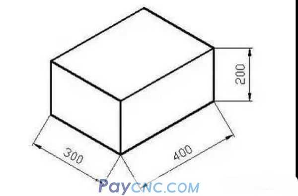
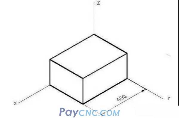
2. The correct label is:
Principles of correct labeling:
(1) The direction of the size numbers is consistent with the direction of the extension line;
(2) The size numbers, the size line and the size extension line are in the same plane.
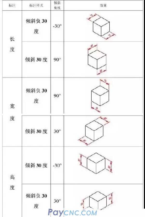
3. Marking method:
(1) Use the "Mark"-"Tilt" menu command, select the 400 size, capture the end of the rectangular parallelepiped as the base point, and give the tilt direction:
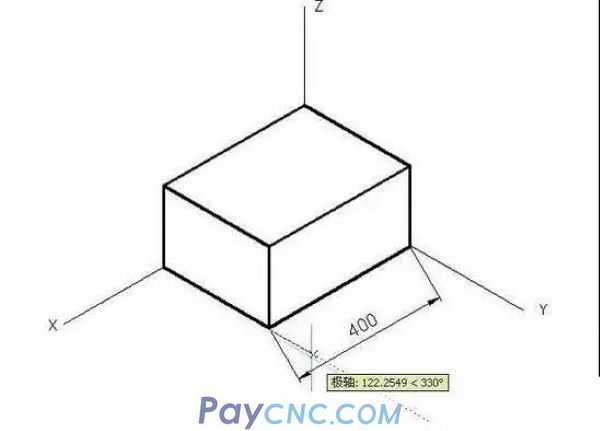
(2) After the confirmation, the extension line is inclined, which meets the labeling requirements, but the size number is still incorrect. The size number should be rotated by -30 degrees at this time:
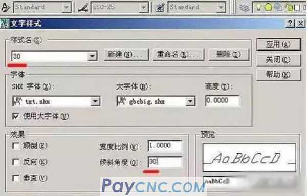
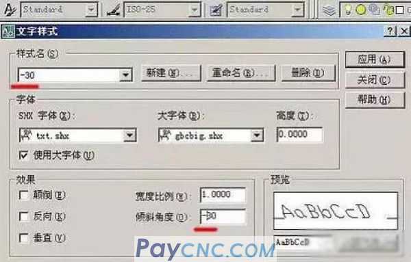
(3) Open "Text Style" and create two new styles, the styles are named "30" and "-30", and the inclination angles are +30 degrees and -30 degrees respectively:
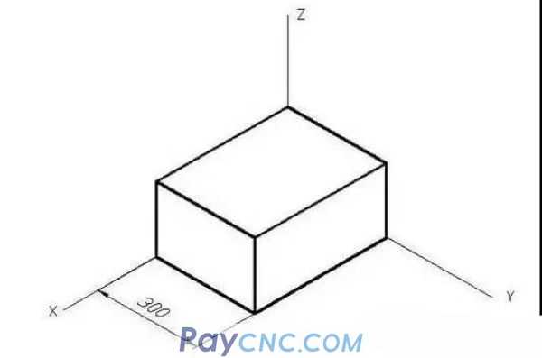
(4) Select 400 size, place it in the text style of -30, and get the correct label immediately:
(5) Also use the "Mark"-"Tilt" menu command to give the tilt direction, and get:
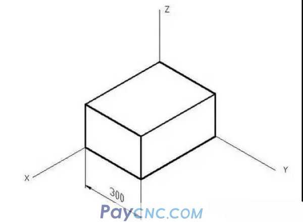
(6) Rotate 400 characters +30 degrees to get the correct label:
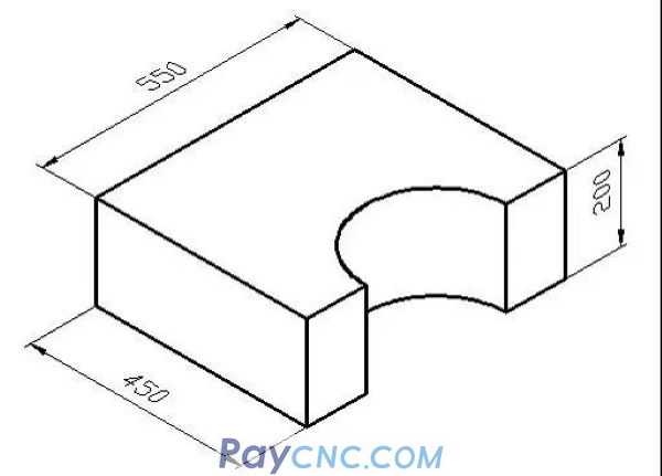
(7) Use the same "tilt" and "rotate" methods to get the correct labeling of the width and height directions:
4. The size of the circle:
(1) The axonometric drawing of a circle is an ellipse and cannot be directly marked:
(2) With the center of the ellipse as the center and the appropriate length as the radius, draw a circle that intersects the ellipse at point A:
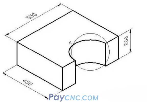
(3) Mark the radius of the circle, and the arrow should be as close as possible to point A, the size is wrong:
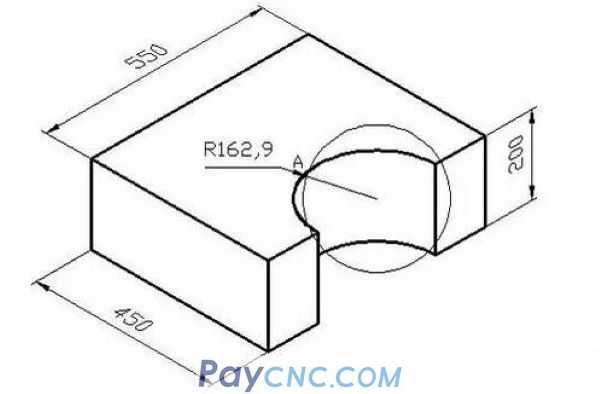
(4) Use the ED command to modify the wrong R162.9, change it to the correct R150, and delete the mark A and auxiliary circle to get the correct mark!
|
 |
| Products Catalogue | Home | About Us | Retrofit | Download | News | Tech Support | Contact Us | |
|
|
|