Introduction to PMC axis control:
The PMC axis control is separated from the CNC management and directly controlled by the PMC signal. The axis movement mode, displacement and speed are not obtained by NC program programming, but are defined in PMC by assigning G address. It can run together with the NC control axis in the same path, and the two have no interpolation relationship and are independent of each other. It is mainly used to control the oscillating action of the tool rest, exchange table, index table and grinder.
Among them, the use of PMC axis to control the tool magazine can not only exert the excellent control characteristics of the servo motor, but also does not need to use the inductive switch to count, so it is more used in actual tool magazine control. Based on the previous experience in debugging the PMC axis tool magazine ladder diagram of the VDU1000 wall-type five-axis machining center in Dalian Machine Tool Plant, this article briefly introduces the PMC axis control method and precautions of PMC axis tool magazine control:
1. PMC axis tool magazine control-parameter setting
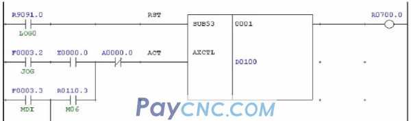
Since the PMC axis needs to perform three-element assignment and buffer processing during programming, the standard function instruction AXCTL (SUB53) of the PMC axis can be used to select the mechanical coordinate system selection (instruction code 20H) to quickly move to the The commanded machine coordinate position is commanded when the tool is moved to a certain machine-specific position such as the tool change position.
parameter settings

Description:
1. The setting of 360 in 1260 has nothing to do with whether there is a deceleration mechanism in the tool magazine. When there is a deceleration mechanism, pay attention to the correct servo setting of the tool magazine motor, otherwise the actual rotation position will be wrong.
2. Set 1008#0 to 1 to enable the cycle function. Otherwise, when the tool magazine is commanded to rotate from the last tool to the first tool, it will not continue to rotate in the original direction, but in the opposite direction.
2PMC axis-ladder diagram realization
2.1 According to the angle
This method generally calculates the angle value between two tool pockets, calculates the rotation angle according to the specified tool pocket number, and controls the rotation of the tool head as a position value. For details, please refer to the "PMC" written by Su Kai in the OA technical document. Axis Function Command AXCTL Application" Click on the bottom of the article [Read the original text] to download the PDF document WeChat Official Account: CNC Notes; the method is described below in conjunction with the ladder diagram in the relevant part of the document.
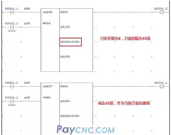 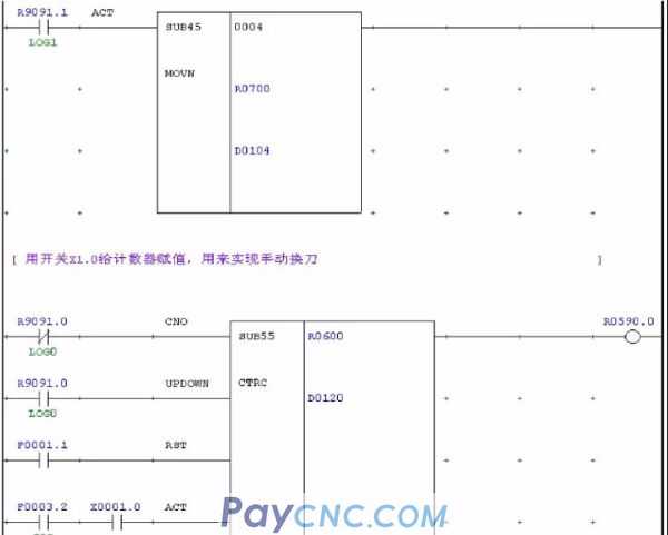 
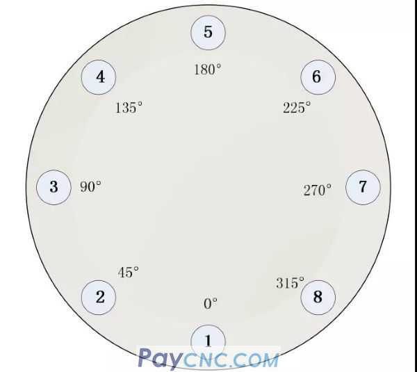
Through this method, automatic and manual cutter head rotation can be realized. Generally, machine tool manufacturers are accustomed to use the position of the first tool as the zero point of the tool magazine. Therefore, the actual tool pocket number and rotation degree are as shown in the figure below. Show. In automatic mode, if the fifth tool is changed, the instruction M06T05 (M06 is to call the macro program), the actual corresponding degree is 180, that is: 45*5-45, therefore, 45 degrees are subtracted by the SUBB function module in the ladder diagram . In manual mode, the tool is selected through X1.1. After the tool selection is completed, X0.0 instructs the tool magazine to rotate to the corresponding tool position.
In practice, there are many manual forward and reverse buttons near the tool magazine, requiring that the tool wheel rotates one tool position every time you press it. In the above situation, the tool selection signal can be replaced by X0.0, and each time X0.0 is pressed , The cutter head rotates one tool position. However, there is a problem with this method: when the last knife is commanded in the automatic mode, switch to manual mode and press X0.0, the cutter head will not rotate, because when the last knife is commanded, the The value is 8, after switching to manual and pressing the button X0.0, D120 will change to 1, and the value in R700 is 0 according to the processing of the ladder diagram, so the cutter wheel does not rotate. At this time, it can be controlled in an absolute position.
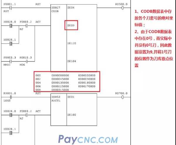
2.2 According to the absolute position method
This method refers to storing the absolute coordinates of each tool pocket number so that the pocket number and absolute position correspond one-to-one. After selecting the corresponding tool number, the system will automatically find the actual position corresponding to the tool number and control it. The cutter head rotates, and the coordinate value of each tool number is stored in the data table through the function command CODB.
The implementation of the ladder diagram is as follows, where:
X28.0: Manual forward rotation button (every press, the counter will increase by 1)
X28.1: Manual reverse key (Each time you press, the counter will decrease by 1)
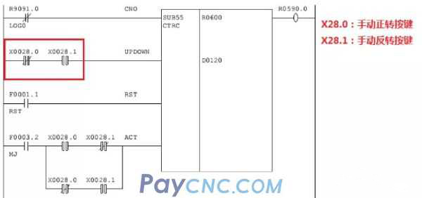 
In this way, arbitrary switching between manual and automatic can be realized without the problem of the cutter head not moving. Because each tool pocket number corresponds to a different coordinate value, the cutter head will rotate to the corresponding position according to the selected tool number.
3 matters needing attention
3.1 Tool magazine capacity is greater than or equal to ten
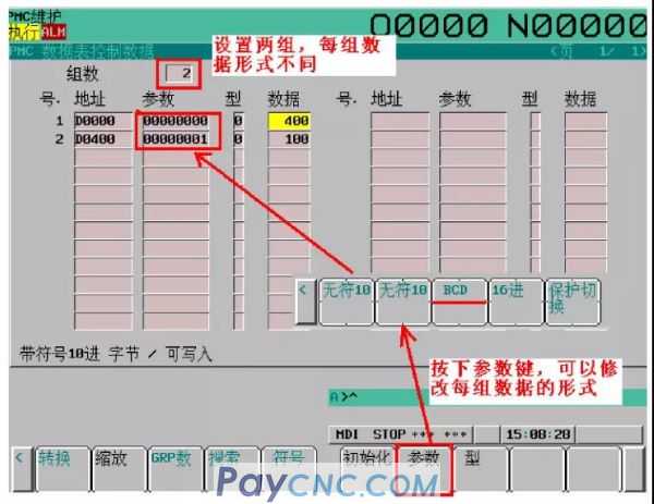
In the PMC axis tool magazine tool change ladder diagram processing, the data addresses used mainly include: spindle tool number, current tool holder number of the tool pot, tool pot capacity, etc. Generally, D address or R address is used. These values are compared. The result is used as the judgment condition in the macro program. The function modules used involve NUMEB, CODB, COIN, COMP, etc. When using these modules, one thing to pay special attention to is whether the data to be compared is in binary or BCD format.
Binary: NUMEB, CODB
BCD code: COIN, COMP
When using these functional modules, pay attention to whether the data types of the two addresses to be compared are the same, because the main differences between binary and BCD codes are:
When the decimal number used to represent is 0-9, the binary code is exactly the same as the BCD code;
When the decimal number used to represent is greater than 9, the binary representation is the sum of the binary digits according to the weight of each bit, and the BCD code is that each decimal digit is represented by 8421BCD code.
Therefore, when performing tool change from 1-9 to tool change, if the compared data format is not the same, there will be no error, and when it is greater than 9, there will be uncertain phenomena such as chaotic tool. In the data table, it is best to set the used data grouping in binary or BCD format to avoid errors in the ladder diagram processing when a certain data is directly assigned an initial value.
3.2 M code end processing
Compared with the general tool change, PMC axis tool changer has no counting switch, so it is impossible to judge whether the cutter head rotation is completed by counting. After the PMC control command AXCTL is written, the output W1 is 1. At this time, the tool changer Rotation is probably not completed, and W1 cannot be used as the end condition. PMC can be used to assign completion signals F112.0~ .4. This signal is issued by PMC and the signal becomes '0' when the axis is moving.
4 summary
In the actual application of PMC axis tool magazine control, both ladder diagram programming methods can be realized. In practice, the difference between the two tool sleeves of some cutter heads cannot be strictly guaranteed to be the same. Therefore, the method according to the degree may make the tool sleeves There is a deviation between the position and the tool change position, and there is a problem when changing the tool; the method of using the absolute position requires measuring the coordinates of each tool holder number. When there are more tools, it will be more troublesome. Which method to use should be based on the site conditions and Determined by the requirements of the machine tool manufacturer.
|
 |
| Products Catalogue | Home | About Us | Retrofit | Download | News | Tech Support | Contact Us | |
|
|
|