Among all the alarms of the FANUC system, the system alarm "SYS ALM" can be regarded as the most mysterious one. The deep black screen background, accompanied by red, yellow, and white English descriptions and alarm codes, is also the most helpless alarm for FANUC users. So, this issue of the document will reveal this mysterious system alarm "SYS ALM" in depth for everyone, let you know what the system alarm is, and let you know how to deal with it, so that you can instantly become FANUC. CNC "Little Superman"!
1SYS ALM alarm definition
When the CNC detects that it cannot maintain the normal operation of the system, it shifts to a special processing state called the system alarm state, which is called the system alarm state.
After entering the system alarm state, the following operations must be performed immediately while switching the CNC screen.
1. Disconnect the excitation of servo and spindle amplifier;
2. Cut off the I/O Link communication;
The types of system alarms can be divided into the following 3 types:
1. Alarm detected by software;
Typical causes of abnormality include: detecting data conflicts based on the processing of the internal state monitoring software, accessing outside the scope of data or commands, dividing by zero, stack overflow, DRAM and data verification errors.
2. Alarm detected by hardware;
The typical abnormal causes are: parity error, bus error, power alarm, FSSB cable disconnection.
3. Other alarms.
Typical reasons are: servo software error, PMC software detection I/O Link communication abnormality.
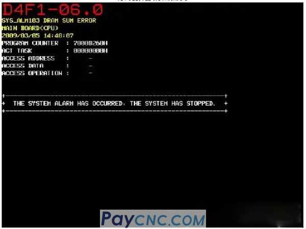
2Operation when encountering SYS ALM alarm
It should be noted that when a system alarm occurs, the system will automatically switch to the home page of the system alarm screen, and the system alarm screen is composed of multiple pages of information, which can be switched by the page up and down keys. By pressing RESET, you can also directly execute the IPL monitoring screen, and then you need to output the system alarm information to the memory card. The specific operations are as follows:
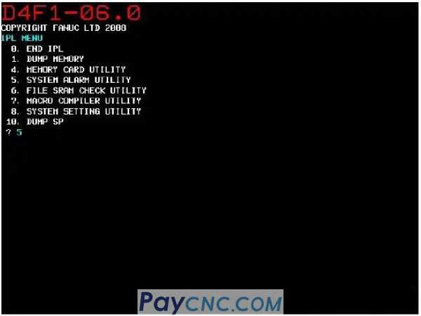
1. Start the IPL monitor;
When the system alarm screen is displayed when a system alarm occurs, press the RESET button, or temporarily disconnect the power supply, press and hold the "." and "-" buttons to power on at the same time.
2. Enter 5 on the IPL monitoring screen and select "5. SYSTEMALARM UTILITY";
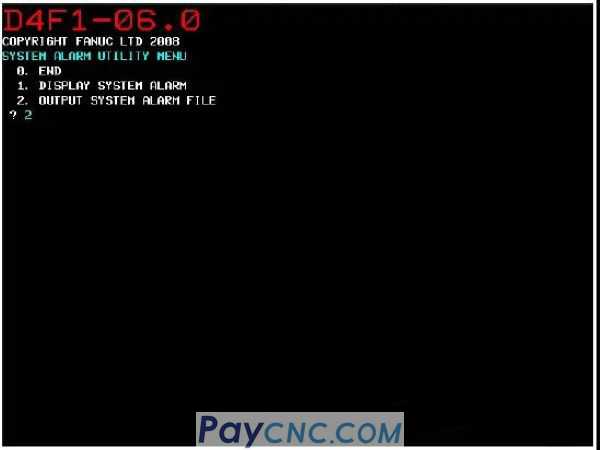
3. Enter 2 and select "2.OUTPUT SYSTEM ALARM FILE";
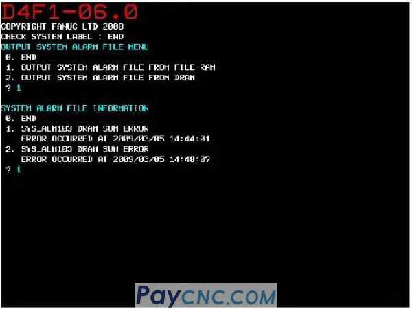
4. When the IPL monitor is executed from the system alarm screen, input 2 and select "2. OUTPUT SUSTEM ALARM FILE FROM DRAM", temporarily disconnect the power supply, input 1, and select "1. OUTPUT SYSTEM ALARM FILE FROM FILE-RAM";
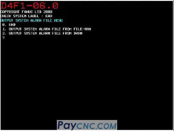
5. When 1 is selected in the 4. option, the saved system alarm list information is displayed, and the file number you want to output can be directly input;
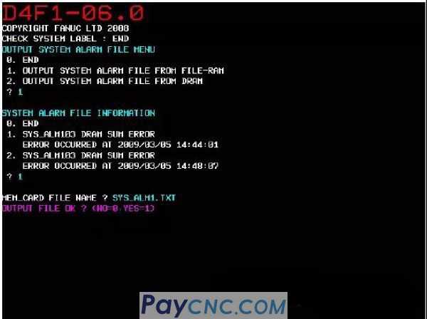
6. Enter the file name to be output to the memory card and execute the output.
Note: All kinds of information when a system alarm occurs are automatically saved in SRAM, and the latest 2 system alarm information can be saved in SRAM. When the third system alarm occurs when the information is saved for the second time, the earliest system alarm is discarded, and the new alarm information is saved.
|
 |
| Products Catalogue | Home | About Us | Retrofit | Download | News | Tech Support | Contact Us | |
|
|
|