1. FSSB definition
FSSB is the abbreviation of FANUC Serial Servo Bus. The FANUC numerical control system connects the CNC, servo amplifiers and separate detectors through optical cables and exchanges high-speed information. Information includes movement instructions, semi-closed loop feedback, fully closed loop feedback, component failure alarm, and ready information. The use of FSSB connection can greatly reduce the cable required for the electrical installation part of the machine tool.
FANUC | Initial setting of FSSB of 0i-F system
FANUC FSSB Intelligent Rigid Tapping Parameters Introduction
FANUC alarm: FSSB related alarm
2. The role of FSSB parameter settings
On the basis of the FSSB hardware connection, the master-slave correspondence between the master controller (CNC controller) and the slave controller (servo amplifier, separate detector, etc.) can be established through the FSSB parameter setting.
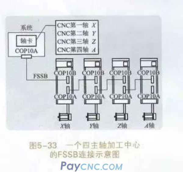
3. FSSB connection composition
Through the FSSB, the master controller (CNC controller) and the slave controller (servo amplifier, separate detector, etc.) are connected with optical cables. The physical connection of FSSB is very regular, from CNC's COP10A to the next slave's COP10B, and so on.
4. The basic steps of FSSB setting
FSSB can be set automatically or manually. If there is no special use requirement, the automatic setting method is generally adopted.
1. Set system parameter 1902#0 and parameter 1902#1 to 0, and execute FSSB automatic setting. The system needs to be powered off and then powered on again to complete the FSSB automatic setting process. The system parameter 1902# is set to 0, which means the automatic setting is executed. After the automatic setting is completed, the result of 1902#1 is 0, which means that the system has not completed the FSSB automatic setting.
2. The FSSB setting page displays the information of the servo amplifier and axis based on FSSB.
 In addition, the information of the servo amplifier and axis can also be set
aPress the function key
b Press the Continue soft key several times to display the menu【FSSB】
c Click [FSSB] to switch to the amplifier setting page, and the following menu will be displayed
FSSB setting page contains 3 pages, amplifier setting page, axis setting page,
When you click the amplifier, it switches to the amplifier setting page. When you click an axis, it switches to the axis setting page. When you click Repair, switch to the amplifier maintenance page
d In the amplifier setting page, the information of each slave control device is displayed in the amplifier and external detector interface unit, and the page can be switched by the page key. The amplifier setting page is shown in Figure 5-34 and Figure 5-35.
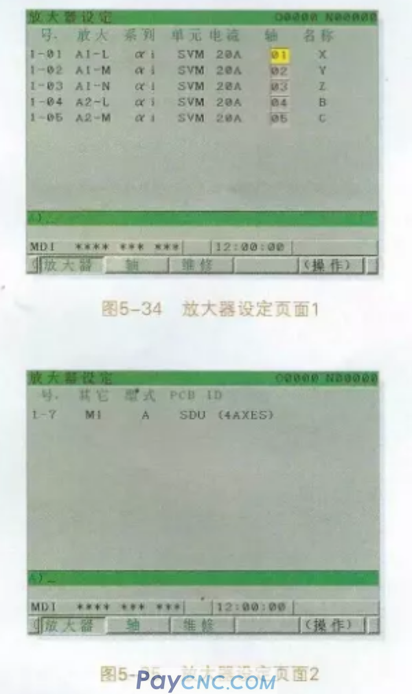
The amplifier setting page is shown in Figure 5-34, and the following items are displayed.
A number-slave control device number
Expressed in nm form, n represents the channel number of the FSSB, n=1 represents the connection interface is COP10A=1; m represents the slave device connected to the FSSB, numbered starting from the closest to the CNC, and each FSSB line displays up to 10 slave controllers. Device.
b zoom-display the type of servo amplifier
The servo amplifier type is composed of characters A+number+characters L/M/N. A represents the servo amplifier, and the number represents the number of the servo amplifier. The number of the servo amplifier closest to the CNC is 1, and L/M/N represents the input of the servo amplifier. To axis (L: 1st axis, M: 2nd axis, N: 3rd axis) In Figure 5-34, A1 represents the first servo amplifier, and A1 can control three servo motors at the same time. Similarly, A2 means the second servo amplifier, which can control two servo motors at the same time
c amplifier information
The servo amplifier information displayed on the amplifier setting page mainly includes the following items
Series-Servo amplifier series, such as ai series, bi series, etc.
Unit-Types of Servo Amplifier Unit
Current-Maximum current value
Servo amplifier information is automatically recognized by the system
d axis-control axis number
The displayed control axis number corresponds to the control axis number of the color number in the system parameter 1023, which is automatically found by FSSB
e name-control axis name
Display the axis name corresponding to the control axis number, set in parameter 1020, when the control axis number is 0, it will display "——"
f The external detector interface unit information displayed on the amplifier setting page is shown in Figure 5-35. If the FSSB is connected correctly, the system will automatically display the information of the following items
other
After the initial letter "M" indicating the external detector interface unit, the number of the external detector interface unit numbered from the side close to the CNC is displayed. In Figure 5-35, M1 represents the first separate detector on the side close to the CNC
Type
The type of the external detector interface unit is displayed in letters
PCBID
In addition, if an external detector interface unit (8 axis) is connected, "SDU" (8AXES) will be displayed in the ID of the external detector interface unit. If an external detector interface unit (4 axis) is connected, the external detector "SDU" (4AXES) is displayed in the ID of the interface unit
If the corresponding relationship between the servo amplifier and the axis shown in Figure 5-34 meets the design requirements, there is no need to modify it. If you want to reset the corresponding relationship between the servo amplifier and the axis, you can modify it on the amplifier setting page.
e-axis setting page
The axis information is displayed on the axis setting page. The axis setting page is shown in Figure 5-36
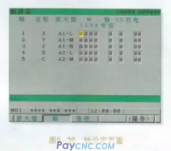
The following items are displayed on the axis setting page
a-axis-control axis number is displayed in the order of the control axis connected by CNC
b name-control axis name
c Amplifier-the type of servo amplifier connected to each axis
dM1-M4- If you use the external detector interface unit (M1-M4) as the servo axis of the position feedback device, you need to set the corresponding connector number, that is, set the specific connector of the position feedback of the servo axis. If the servo axis of the external detector interface unit is not used, it will be displayed as 0. If the servo axis of the external detector interface unit is used, the parameter 1815#1=1 should be set.
e-axis exclusive-set the maximum number of axes controlled by a DSP for HRV3. 0, which means there is no limit
f CS-If the spindle is set to servo axis control, called CS contour control axis, set the spindle number (1 or 2) at CS, if there is no CS contour control axis, set CS to 0.
g Double Electric-Install a servo motor on the coordinate axis, which doubles the moving torque in this direction and becomes a double electric control. Set the axis with two servo motors to serial motion control, the master axis is set to an odd number, and the slave axis is set to an even number. If dual electric control is not used, set it to 0.
f. In the FSSB setting page (except the amplifier maintenance page), click [Operation] to display the following menu
When inputting data, set to MDI mode or emergency stop state, move the cursor to the position of the input item, and click [Input] after inputting the data. The amplifier setting page is shown in Figure 5-37
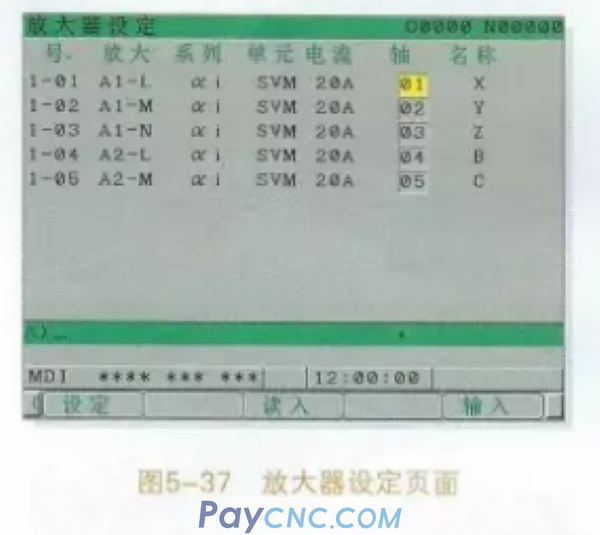
The axis number can be set in the amplifier setting page. As shown in Figure 5-37, if you want the optical cable connection position to remain unchanged, but the function definition of connecting the servo motor is changed, just change the serial number in the axis column. For example: after initialization, A1-L corresponds to the X axis, and A1-M corresponds to the Y axis. Now to make A1-L correspond to the Y axis, and A1-M correspond to the X axis, just set 02 in the row axis parameter corresponding to A1-L. Set 01 in the corresponding row axis parameter of A1-M, no need to physically change the wiring. Sometimes the method used when using the comparative method for maintenance
g axis setting page
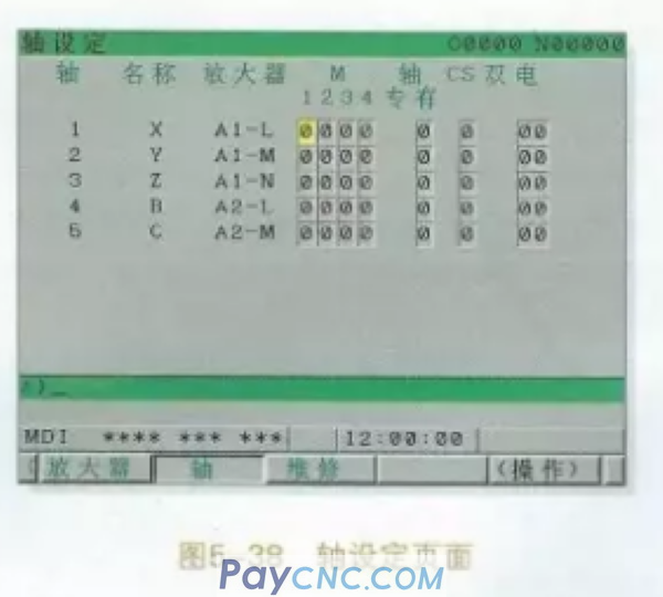
Click the axis, then click operation, the axis setting page is shown in Figure 5-38
The semi-closed loop servo control system generally does not need to set the parameters shown in Figure 5-38, just set the parameters to 0. The full closed loop should be set according to the connection number used for the external detector interface unit
3. According to the information on the display, it may be necessary to power off and then power on to make the parameter settings take effect
case study
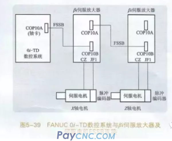
The connection between FANUC Oi-TD CNC system and bi servo amplifier and servo motor FSSB is shown in Figure 5-39. The axis card of the numerical control system is connected to the COP10B of the first servo amplifier by an optical cable, and then the first servo amplifier COP10A is connected to the COP10B of the second servo amplifier by an optical cable. Each axis is defined as the Z axis. The FSSB setup process is as follows
1. In MDI mode, press the emergency stop case, then press the function key, click set, select the setting page, confirm the write parameter=1. Set the system parameter 1902#0 and parameter 1902#1 to 0 , Execute FSSB automatic setting, set the system parameter 1902#0 to 0, then power off and power on
2. Press the function key
3. Press the Continue soft key several times to display the menu FSSB
4. Click FSSB to switch to the amplifier setting page, and the following menu will be displayed
5. When you click the amplifier, switch to the amplifier setting page. As shown in Figure 5-37, if the connection is not changed, the FSSB optical cable can automatically find the servo amplifier and the corresponding servo motor. The first servo amplifier corresponds to the X axis, and the second servo amplifier corresponds to the Z axis. If you want the first servo amplifier to correspond to the Z axis and the second servo amplifier to correspond to the X axis, then you can set 02 on the axis parameter corresponding to the first servo amplifier on the amplifier setting page as shown in Figure 5-37. Set 01 at the axis parameter corresponding to the first servo amplifier
6. When you click the axis, switch to the axis setting page. As shown in Figure 5-38, because it is a semi-closed loop, all parameters in the axis setting page are set to 0.
7. Press the function key, then click set, select the setting page, confirm that the write parameter=0, then press RESET, the CNC is powered off and then powered on again.
|
 |
| Products Catalogue | Home | About Us | Retrofit | Download | News | Tech Support | Contact Us | |
|
|
|