 Use of diagnostic functions
After the CNC system fails, if there is no alarm information, the fault is judged through the system's diagnostic screen. When the machine tool is abnormal in the diagnosis screen of the system, the alarm signal and monitoring data provided by the diagnosis function provide a basis for the fault judgment.
Diagnose faults with diagnostic functions
How to effectively use the diagnostic information provided by the diagnostic function to help find and troubleshoot? This must be our biggest concern. Next, learn how to use the diagnostic function to solve some hidden faults that often appear in practice.
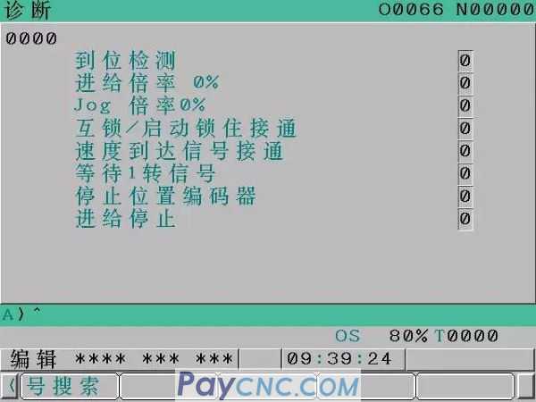
(1) When the diagnosis number 000 is 1, it indicates that the system is executing auxiliary functions (M commands). During the execution of the auxiliary function, No. 000 will remain at 1 until the signal arrives when the auxiliary function is completed. Therefore, when the execution time of the auxiliary function exceeds the normal value, it may be that the condition of the auxiliary function is not met. Therefore, there is an abnormality without alarm. When searching for the fault point, if the diagnosis number 000 is 1, you can first check whether the machine tool action to be completed by the auxiliary function has been completed.
Trouble phenomenon: When a CNC machine tool is in the automatic running state, whenever the auxiliary function instruction M8 (cutting fluid spray) is executed, the processing program is no longer executed. At this time, cutting fluid is sprayed from the pipeline, and the system does not have any alarm prompt.
Remedy: Call up the diagnosis function screen and find that the diagnosis number 000 is 1, which means that the system is executing the auxiliary function, and the auxiliary function of cutting fluid spray has not been executed (it is not possible to confirm whether the cutting fluid has been sprayed in the system, In fact, the cutting fluid has been sprayed out). Therefore, I checked the electrical catalog and found that there is a flow switch on the cutting fluid pipe to confirm whether the cutting fluid has been sprayed. While executing the M8 command and confirming that cutting fluid is sprayed, check the input point X2.2 of the flow switch in the signal status monitoring screen of the PMC program and the status of this point is 0 (it should be 1 when there is spray ), so the fault point can be determined as the flow switch fails to operate normally while cutting fluid is sprayed normally. Therefore, readjust the sensitivity of the flow switch and spray lubricant on its action mechanism to prevent inflexible action and ensure reliable action. After making the above treatment, carry out trial operation and trouble shooting.
(2) When the diagnosis number 003 is 1, it indicates that the system is checking whether the moved servo axis is accurately positioned to the command value. When the servo axis fails to achieve accurate positioning, the diagnosis number 003 will be 1 for a long time.
Trouble phenomenon: A CNC machine tool often stops unexpectedly during automatic processing. Especially after the Z axis moves, there are more sneak stops. After this phenomenon occurs, the processing program will not be executed down, but after several tens of seconds, the processing program will be executed again. Sometimes it does not work, and the machine tool has been stunned without sending any alarm information.
Remedy: In the absence of any alarm information, call up the diagnosis function screen, hoping to find a clue to the failure. When checking the diagnosis function screen, it is found that the diagnosis number 003 is in-position detection and the signal is 1, so check the real-time command and actual position deviation of each servo axis with the diagnosis number 300, and find the real-time command of the Z axis and the actual position deviation The value of the value is 50 and the allowable deviation value (in-position width) of positioning is set by parameter 1826, that is to say, as long as the deviation between the real-time command and actual position of each servo axis with diagnosis number 300 does not exceed the setting in parameter 1826 If the value of, the system will consider that the positioning of the servo axis is completed, otherwise, the system will consider that the positioning of the servo axis is not completed, so it performs repeated positioning and the processing program cannot be executed. In parameter 1826 of this machine, the in-position width value of the Z-axis is 4, so the actual position deviation of the Z-axis is greater than the in-position width value set by the parameter, so this failure phenomenon occurs. Parameter 1825 is the servo loop gain of each axis, and the relationship with the position deviation is:
Position deviation = feed speed/60×servo loop gain
According to this formula, the Z-axis servo loop gain value can be appropriately reduced, thereby reducing the amount of position deviation. After making appropriate adjustments to parameter 1825, the position deviation of the Z axis is reduced to 1, that is, the position deviation is less than the setting value of parameter 1826, and the fault is eliminated.
(3) When the diagnosis number 005 is 1, it indicates that the system is in the interlock of each servo axis or the start lock signal is input, which prohibits the movement of each servo axis of the machine tool. All axes of the machine tool or each servo axis fail to meet the moving conditions, or there will be a dangerous situation if the servo axis moves. When the servo axis interlock signal of the following PMC is 0, the machine tool enters the servo axis interlock state, that is, movement is prohibited:
G8.0 (forbid all servo axes to move)
G130.0 (forbid the movement of the first servo axis defined by the system)
G130.1 (Prohibit the movement of the second servo axis defined by the system)
G130.2 (Prohibit the movement of the third servo axis defined by the system)
G130.3 (Prohibit the movement of the fourth servo axis defined by the system)
G132.0 (Prohibit the positive movement of the first servo axis defined by the system)
G132.1 (Prohibit the positive movement of the second servo axis defined by the system)
G132.2 (Prohibit the positive direction movement of the third servo axis defined by the system)
G132.3 (Prohibit the positive movement of the fourth servo axis defined by the system)
G134.0 (forbidden to move in the negative direction of the first servo axis defined by the system)
G134.1 (forbid the movement of the second servo axis defined by the system in the negative direction)
G134.2 (Prohibit the movement of the third servo axis defined by the system in the negative direction)
G134.3 (Prohibit the movement of the fourth servo axis defined by the system in the negative direction)
Trouble phenomenon: During the automatic operation of a special CNC machining machine, when the program reaches G90G01Z0;, it stops for no reason. Perform a system reset and restart the processing program again, and it will also execute to G90G01Z0; this program stops the action. At this time, there is no alarm information.
Remedy: In the absence of any alarm information, call up the diagnosis function screen, hoping to find a clue to the failure. When checking the diagnosis function screen, it is found that the diagnosis number 005 system is in the interlock of each servo axis or the start lock signal is input as 1. So check the servo axis interlock signal of the above PMC, and find that G130.0 is 0, and the Z axis is the first axis defined in the system, consult the ladder diagram, take a look at the reason why the coil G130.0 failed to connect, and finally found The status of the detection proximity switch for the turret lift/fall is 1 at the same time. The inspection found that the turret actually fell into place, and the proximity switch for the detection of the lift sent out a false signal because of the iron filings, so the PMC program judged The conditions for safe movement of the Z axis are not met. After cleaning the proximity switch, the coil G130.0 is set to 1, the interlocking state of the Z axis is released, and the fault is eliminated.
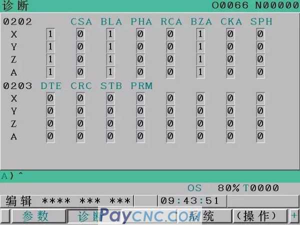
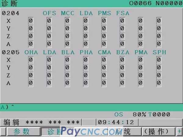
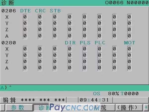
(4) No. 350 alarm, which is caused by an abnormality in the control part of a serial pulse encoder. At this time, the alarm status displayed by the diagnosis numbers 202 and 204 in the diagnosis function can be used to determine the specific cause of the failure.
(5) No. 351 alarm, which is caused by abnormal communication between a serial pulse encoder and the module. At this time, the alarm status displayed by the diagnosis number 203 in the diagnosis function can be used to determine the specific cause of the failure.
(6) No. 400 alarm is caused by the system detecting that the servo module or servo motor is overheated. At this time, the alarm status displayed by the diagnosis number 200 and 201 in the diagnosis function can be used to determine the specific cause of the fault.
(7) Alarm No. 414 is caused by an abnormality in the servo module or servo motor. At this time, you can use the alarm status displayed by the diagnostic numbers 200, 201 and 204 in the diagnostic function, and the alarm number displayed by the LED on the servo module to determine the specific cause of the fault.
(8) No. 416 alarm, which is caused by the signal disconnection or short circuit of the position detector. At this time, the alarm status displayed by the diagnosis numbers 200 and 201 in the diagnosis function can be used to determine the specific cause of the fault.
(9) No. 417 alarm is caused by abnormal system servo parameter setting. At this time, the alarm status displayed by the diagnosis numbers 203 and 280 in the diagnosis function can be used to determine the specific cause of the fault.
(10) Alarm No. 749 is caused by an abnormality in the spindle servo module. At this time, the alarm status displayed by the diagnosis number 408 in the diagnosis function can be used to determine the specific cause of the failure.
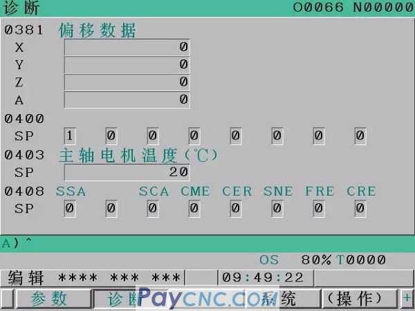
(11) No. 750 alarm, which is caused by the spindle servo module not reaching the normal starting state when the serial spindle system is powered on. At this time, the alarm status displayed by the diagnosis number 409 in the diagnosis function can be used to determine the specific cause of the fault.
3. No handwheel operation
If the handwheel cannot be operated, there may be the following reasons:
The servo is not activated (not ready).
The hand pulse generator is not correctly connected to the built-in I/O interface or I/O module.
The built-in I/O interface or I/O link of the I/O module is not allocated or is not allocated correctly.
The relevant signal is not input due to parameter setting error.
Take measures:
1) Check whether the LED display on the servo amplifier is "0". If a number other than "0" is displayed, it means that the servo is not activated.
2) Check whether the cable is broken or short-circuited;
3) Check whether the handwheel is faulty (whether the signal of the hand pulse generator is correct)
4) Check the I/OLink distribution of the I/O module
5) Check the parameters and input signal
In the lower left corner of the CRT, check that the CNC status should be in the HND status, otherwise, the method selection is incorrect. Further through the PMC diagnosis function (PMCDGN) view mode selection: the handwheel mode is G0043 "MD4=1, MD2=0, MD0=0"
Check the handwheel feed axis selection signal
Check the handwheel feedrate override selection and PCDGN of PMC to confirm the signal: G0019 MP2 and MP1 bits.
The MPG feed of the indexing axis of the indexing table cannot be executed.
|
 |
| Products Catalogue | Home | About Us | Retrofit | Download | News | Tech Support | Contact Us | |
|
|
|