Ordinary machining programs directly specify G codes and moving distances with numerical values; for example, GO1 and X100.0. When using a user macro program, the value can be specified directly or with a variable. When using variables, the variable value can be changed by program or by operation on the MDI panel.
#1=#2+100
G01 X#1 F300
Description:
Variable representation
The computer allows the use of variable names, but not user macro programs. Variables are designated by the variable symbol (#) and the following variable number.
For example: #1
Expressions can be used to specify variable numbers. At this time, the expression must be enclosed in parentheses.
For example: #[#1+#2-12]
Variable type
Variables can be divided into four types according to the variable number
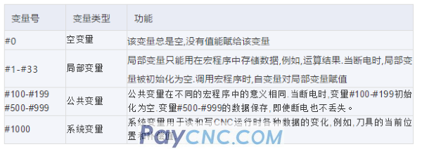
Variable value range
Local variables and public variables can have a value of 0 or values in the following range:
-1047 to -10-29 or -10-2 to -1047
If the calculation result exceeds the valid range, P/S alarm NO.111 will be issued.
Omission of decimal point
When defining variable values in the program, the decimal point can be omitted.
Example: When definition #1=123; the actual value of variable #1 is 123.000.
Variable reference
To use variable values in the program, specify the address followed by the variable number. When specifying a variable with an expression, put the expression in parentheses.
For example: G01X[#1+#2]F#3;
The value of the referenced variable is automatically rounded according to the minimum setting unit of the address.
E.g:
When G00X#/; is executed in the unit of 1/1000mm, CNC assigns 123456 to variable #1, and the actual command value is G00X12346.
To change the sign of the value of the reference variable, put the minus sign (-) in front of #.
For example: G00X-#1
When referencing undefined variables, the variables and addresses are ignored.
For example: when the value of variable #1 is 0 and the value of variable #2 is empty, the execution result of G00X#1 Y#2 is G00X0.
Common variables of dual-track (dual-track control)
For dual trajectory control, the system provides a separate macro variable for each trajectory. However, according to the settings of parameters No. 6036 and 6037, some common variables can be used for two trajectories at the same time.
Undefined variable
When the variable value is undefined, such a variable becomes an empty variable. Variable #0 is always an empty variable. It cannot write, only read.
Quote
When referencing an undefined variable, the address itself is also ignored.

(b) Calculation
Except for assignment with <empty>, <empty> is the same as 0 in other cases.

(c) Conditional expression
The <empty> in EQ and NE is different from 0.

limit
Program number, sequence number and optional block jump number cannot use variables.
Example: Variables cannot be used in the following situations:
0#1;
/#2G00X100.0;
N#3Y200.0;
2. Arithmetic and logical operations
The operations listed in the following table can be performed in variables. The expression on the right side of the operator can contain constants and or variables composed of functions or operators. Variables #j and #k in the expression can be assigned with constants. The variable on the left can also be assigned with an expression.
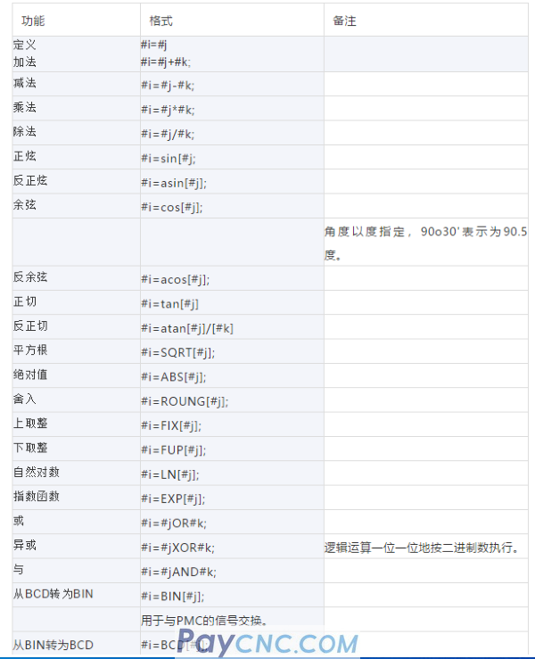
Description:
Angle unit
The angle unit of the functions SIN, COS, ASIN, ACOS, TAN and ATAN is degrees. For example, 90°30' means 90.5 degrees.
ARCSIN # i= ASIN[#j]
(1) The value range is as follows:
When the parameter (NO.6004#0) NAT bit is set to 0, 270°~90°
When the parameter (NO.6004#0) NAT bit is set to 1, -90°~90°
(2) When #j exceeds the range of -1 to 1, P/S alarm NO.111 will be issued.
(3) Constant can replace variable #j
ARCCOS #i=ACOS[#j] The value range is from 180°~0° When #j exceeds the range of -1 to 1, P/S alarm NO.111 will be issued. Constants can replace variable #j
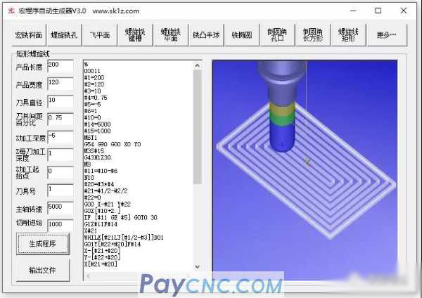
Three, examples
a. Milling oval:
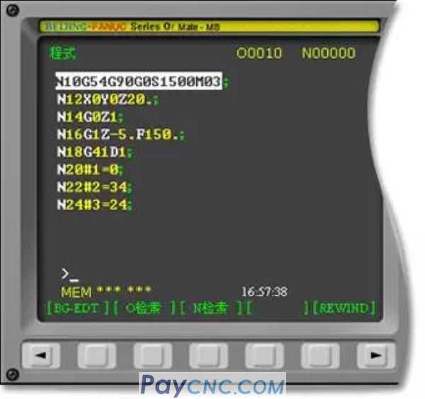
Milling ellipse track:
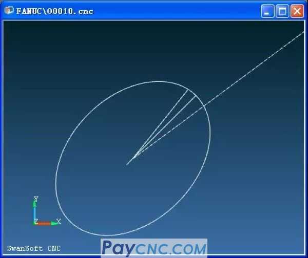
The ellipse program code is as follows:
N10 G54 G90 G0 S1500 M03
N12 X0 Y0 Z20.
N14 G0 Z1
N16 G1 Z-5. F150.
N18 G41 D1
N20 #1=0
N22 #2=34
N24 #3=24
N26 #4=#2*COS[#1]
N28 #5=#3*SIN[#1]
N30 #10=#4*COS[45]-#5*SIN[45]
N32 #11=#4*SIN[45]+#5*COS[45]
N34 G1 X#10 Y#11
N36 #1=#1+1
N38 IF [#1 LT 370] GOTO26
N40 G40 G1 X0 Y0
N42 G0 Z100
N44 M30
b. Milling rectangular slot:
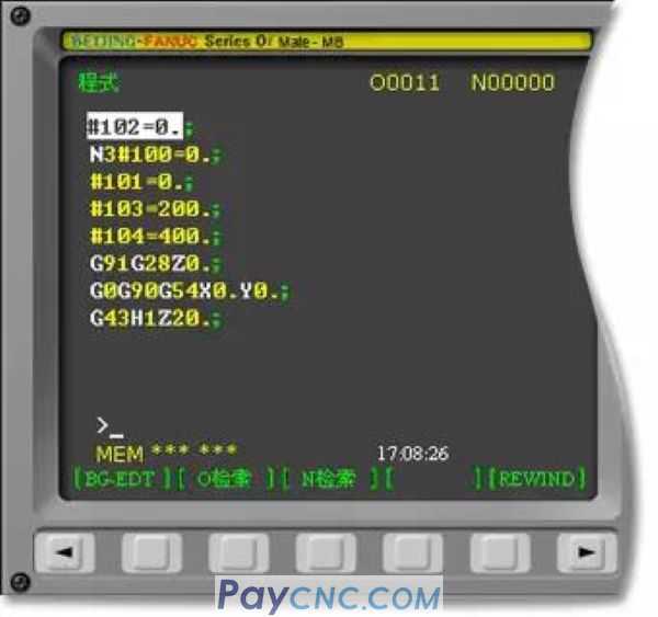
Milling rectangular groove track:
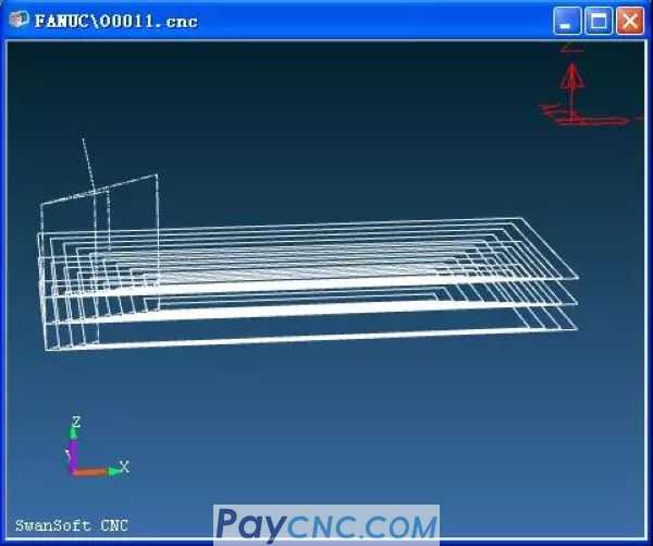
The code for milling rectangular slots is as follows:
#102=0.
N3#100=0.
#101=0.
#103=200.
#104=400.
G91G28Z0.
G0G90G54X0.Y0.
G43H1Z20.
M3S2000.
N4G0X#100Y#101
G01Z#102F200.
#102=#102-2.
IF[#102EQ-50.]GOTO1
GOTO2
N2
N4X#104F500.
Y#103
X#100
Y#101
#100=#100+10.
#101=#101+10.
#103=#103-10.
#104=#104-10.
IF[#100EQ100.]GOTO3
GOTO4
N3
N1
M5
M9
G91G28Z0.
G28Y0.
M30
c. Milling a 3 degree inclined surface:
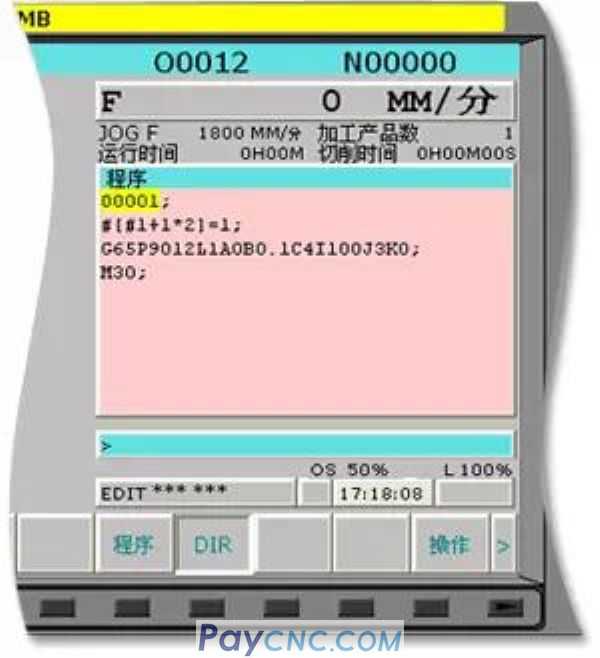
Milling a 3 degree trajectory:
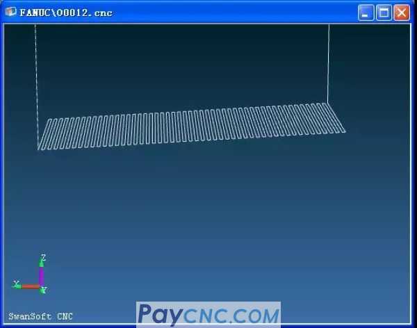
The code for milling a 3 degree inclined surface is as follows:
O0001
#[#1+1*2]=1
G65P9012L1A0B0.1C4I100J3K0
M30
The macro program O9012 code is as follows:
G54 G90 G00 X[#3] Y0 Z100
S500 M3
G01 Z0 F300
WHILE[#1LE10]DO1
#7= #1/TAN[#5]+#3
G1Z-#1 X#7
#8=#6/2-ROUND[#6/2]
IF[#8EQ0]GOTO10
G1Y0
GOTO20
N10 Y#4
N20#1=#1+#2
#6=#6+1
END1
G0
Z100
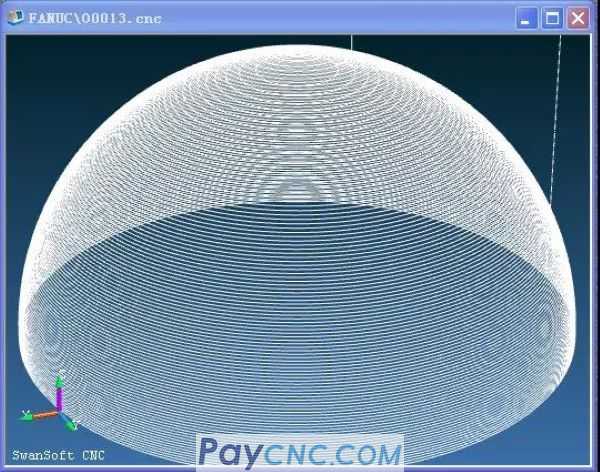
d. Milling hemisphere:
Milling hemisphere track: Milling hemisphere track:
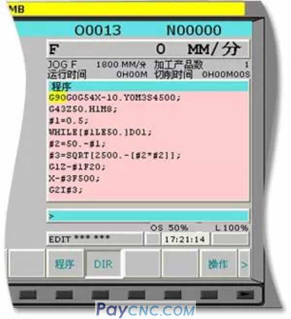
The milling hemisphere code is as follows:
G90G0G54X-10.Y0M3S4500
G43Z50.H1M8
#1=0.5
WHILE[#1LE50.]DO1
#2=50.-#1
#3=SQRT[2500.-[#2*#2]]
G1Z-#1F20
X-#3F500
G2I#3
#1=#1+0.5
END1
G0Z50.M5
M30
e. Milling horn:
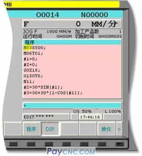
Milling horn track:
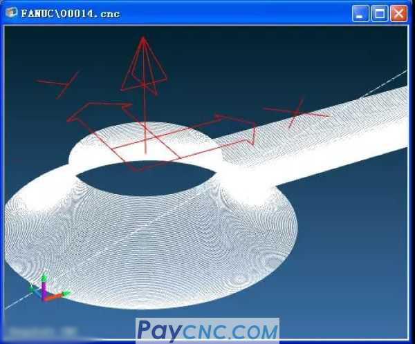
The milling horn code is as follows:
M03 S500
M06 T01
#1=0
#2=0
G0 Z15
X150 Y0
N11
#2=30*SIN[#1]
#3=30+30*[1-COS[#1]]
G01 Z-#2 F40
G41 X#3 D01
G03 I-#3
G40 G01 X150 Y0
#1=#1+1
IF [#1 LE 90] GOTO 11
G0 Z30
M30
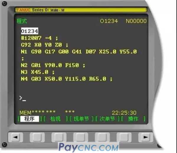
f. FANUC tool compensation system parameter macro program application:
FANUC tool compensation path:
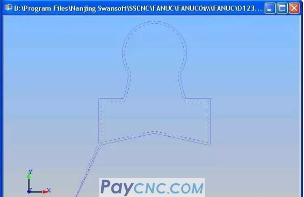
FANUC tool compensation codes are as follows:
O1234
#12007=4
G92X0Y0Z0
N1G90G17G00G41D07X25.0Y55.0
N2G01Y90.0F150
N3X45.0
N4G03X50.0Y115.0R65.0
N5G02X90.0R-25.0
N6G03X95.0Y90.0R65.0
N7G01X115.0
N8Y55.0
N9X70.0Y65.0
N10X25.0Y55.0
N11G00G40X0Y0
|
 |
| Products Catalogue | Home | About Us | Retrofit | Download | News | Tech Support | Contact Us | |
|
|
|
