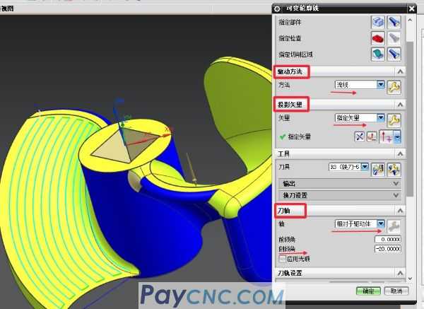
 Summarize the settings of some key parameters of five-axis programming. This article is suitable for students who have mastered three-axis programming and five-axis basic theoretical knowledge and try to continue to learn five-axis programming. Three parameters at the core of five-axis programming: drive method, projection vector, and tool axis.
Driving method: Commonly used methods include streamlines (more intelligent), curved surfaces (setting cutting direction, stepping moment, cutting mode and other parameters), boundaries, etc. After the driving method is determined, select the driving geometry and use the driving geometry to generate the first "virtual" Toolpath", and observe the rationality of the toolpath, and then optimize it.
Projection vector: After the first "virtual tool path" is generated, how it is projected onto the workpiece geometry? The projection method will affect the display quality of the final tool path on the surface of the workpiece, but it has nothing to do with the tool posture. (The so-called tool posture: the three-axis tool is vertical, and the multi-axis tool is inclined). If the projection is not correct, the tool path will display chaos, for example, the tool path is a zigzag line.
Generally speaking, projection vector options are relatively few, often selected, tool axis (the tool path projects the surface of the tool workpiece along the direction of the tool axis), vertical driving body (driving geometry), designated vector, etc. The projection principle of the above methods is simple to understand and easy to operate.
Tool axis: It is discussed in which posture the tool "walks" on the final tool path during processing. The tool posture can be divided into: fixed tool axis, one axial change, two axial changes, etc. There are many options for the tool axis , The following is the classification. Friends who are learning UG programming can join the group to learn
Keep away from the straight line, use the open area surface or the revolving surface, the tool posture of each tool path has a direction change, and the tool posture points to a straight line, and the tool path is generated in accordance with the change of the processing direction. If there is interference from the workpiece, this method will have limitations.
Far away from the point, it is best to use a closed area. The attitude of the tool on each path changes in two directions, and the attitude changes greatly, so this method will have limitations.
The vertical drive body will generate a tool path with the attitude of the tool perpendicular to the area face at all times according to the situation of the selected area. If it is a straight inclined plane, the tool attitude is fixed and the tool path is neat. If it is a curved surface, the tool attitude will change at any time, and The roll angle cannot be specified. If the tool interferes with the workpiece structure and the tool posture cannot be adjusted, this method will have limitations.
Compared with the driving body, it is more flexible than the vertical driving body. If the machining surface is a curved surface, the attitude of the tool during processing will change at any time, and the roll angle can be specified. If there is interference between the tool and the workpiece structure, the roll angle can be adjusted to avoid it. The method is relatively flexible.
4-axis, perpendicular to the driving body/relative to the driving body, use a closed area such as a revolving body structure to generate a tool path of full-circle motion, and change the roll angle, forward angle, etc. This method is simple and convenient.
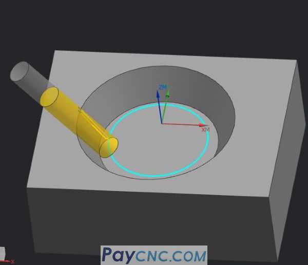
Side edge drive, use the side edge of the tool to incline and cut the inclined side wall, and specify the side edge direction as upward (the purpose is to make the tool posture upward). If the side wall is a straight inclined surface, the tool posture remains unchanged, and the side wall is curved, and the tool is processed The attitude will change during the process, and the roll angle can be specified to continue to change the attitude. This method is relatively flexible.

Contour milling is used for milling oblique and straight walls, using the known bottom surface to automatically find the oblique wall to be machined. Surface milling is not possible (milling a curved surface with a side edge drive), which is similar to the side edge drive. It generates a single tool path similar to plane milling, but it can be used to transform multiple tool paths.
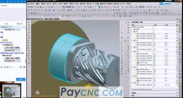
Finally, multi-axis programming is mainly based on the surface structure and processing requirements of the workpiece, and is matched with the five-axis machine tool model to avoid interference with the workpiece, optimize the tool posture, and reasonably generate processing toolpaths. Programming itself is not difficult to master, but the processing technology is demanding.
 |
 |
| Products Catalogue | Home | About Us | Retrofit | Download | News | Tech Support | Contact Us | |
|
|
|