 Introduction: Mechanical systems usually have large component tolerances, assembly gaps, component friction, and certain dynamic balance imbalances, which will produce mechanical natural vibration. The power supply of the servo unit driving the motor is a high-frequency chopper power supply. When the vibration frequency of the motor at a certain speed is close to the natural vibration frequency of the machine, resonance may occur. At this time, a notch filter can be set to suppress resonance.
01Notch filter application description
The notch filter can reduce the gain of a specific frequency to suppress mechanical resonance. To use the notch filter correctly, it must reach the exact resonance frequency, and the situation where the resonance frequency often shifts cannot be applied, so the notch filter is suitable for medium frequency resonance occasions;
Although the larger the width of the notch filter and the smaller the depth parameter value, the stronger the suppression of resonance, but it will cause phase lag and may make the system unstable. Therefore, it is only necessary to modify the parameters appropriately to suppress the vibration.
02GR upper notch filter related parameter description
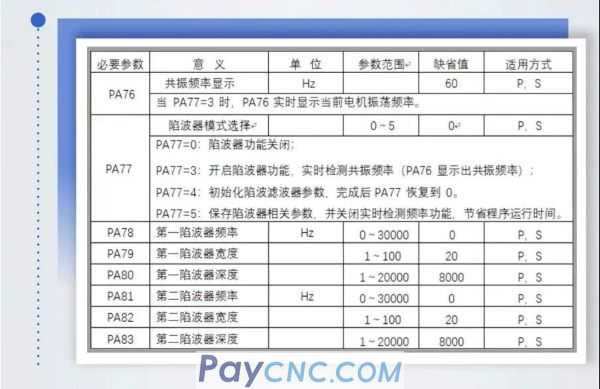
The main points of using the notch filter on the 03GR
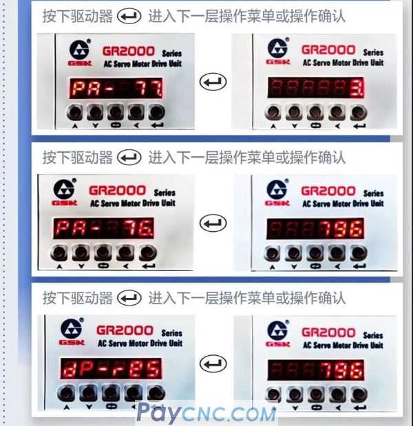
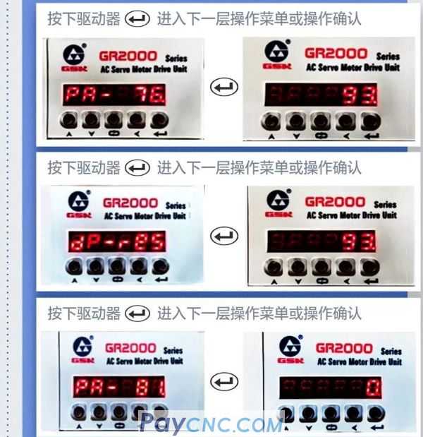
PA77=3, the servo unit turns on "real-time detection of resonance frequency", and the detected frequency is displayed in PA76 parameters and dp-g5.
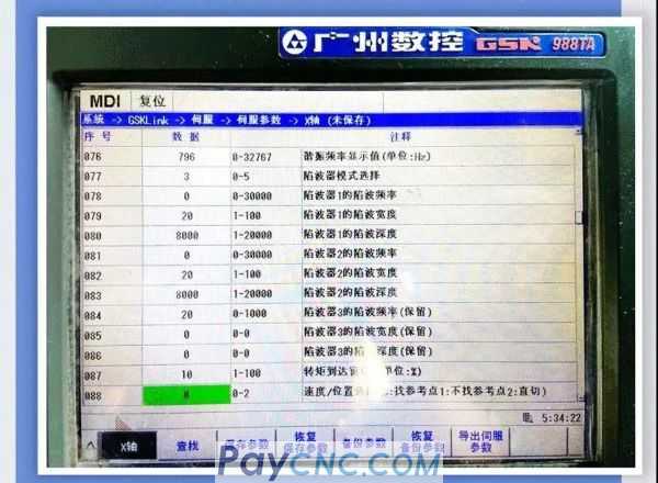
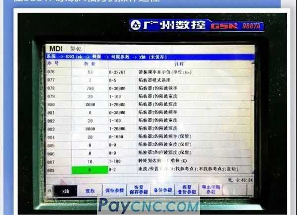
In the 988TA system X axis as an example operation process
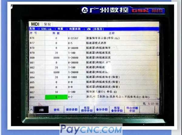
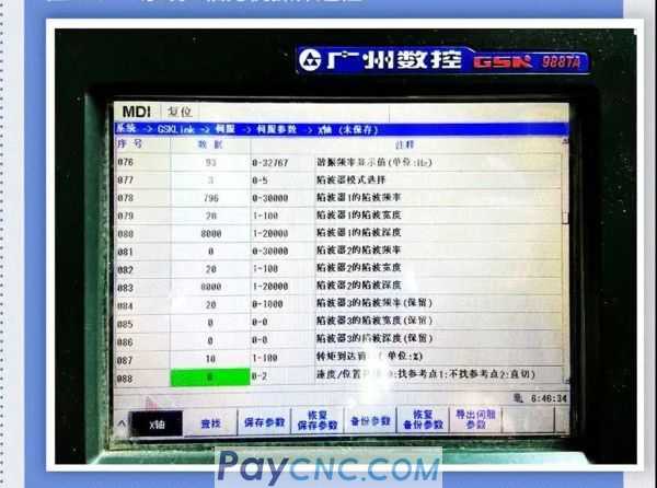
System-GSKLink-servo-servo parameters-X axis. Change the serial number 077 data to 3 and run a circle, the serial number 076 data is automatically modified to 796.
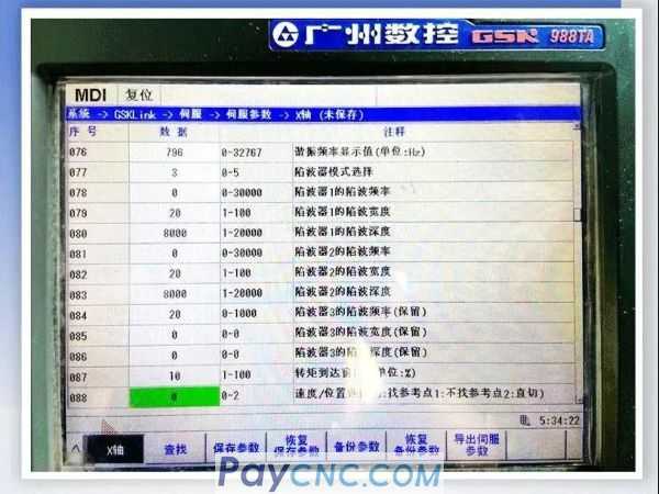
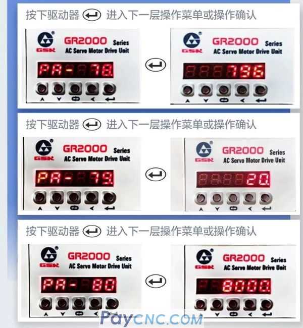
It can also be operated directly in the drive
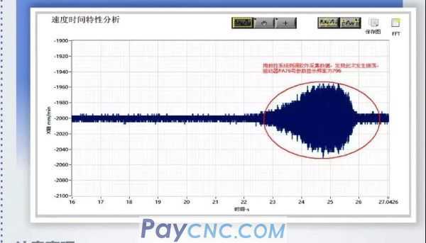
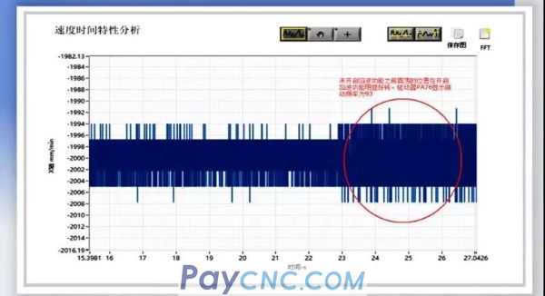
Data collection diagram of CNC system measurement and adjustment software
Precautions
1. The driver has a long program running time due to real-time calculation, and the LED display will flicker, which is normal;
2. It is recommended that the machine tool run the entire stroke in order to obtain the resonance frequency with the largest amplitude.
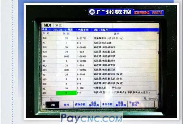
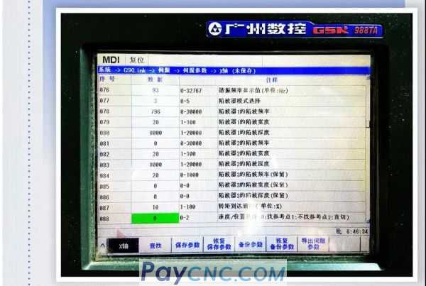
Write the frequency value displayed by PA76 into PA78, then resonance suppression can be performed; take the X axis of the 988TA system as an example operation process
System-GSKLink-servo-servo parameters-X axis. After modifying the serial number 078 data to 796, run a circle, the serial number 076 data is automatically modified to 93.
It can also be operated directly in the drive
Data map of CNC system measurement and adjustment software
After the first set of frequency suppression arcs, the servo unit still automatically detects the resonance frequency, and the detected frequency will still be displayed in PA76 and dp-g5. If there is a big difference from the previous frequency, the frequency value can be written into PA81 to proceed. The second set of resonance suppression. If PA76 or dp-g5 shows a value below 100, there is no need to perform the second set of resonance suppression.
Take the 988TA system X axis as an example operation process
Because the serial number 076 data is lower than 100 after passing through the first set of notch filters, the serial number 081 data does not need to be operated.
It can also be operated directly in the drive
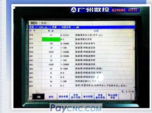
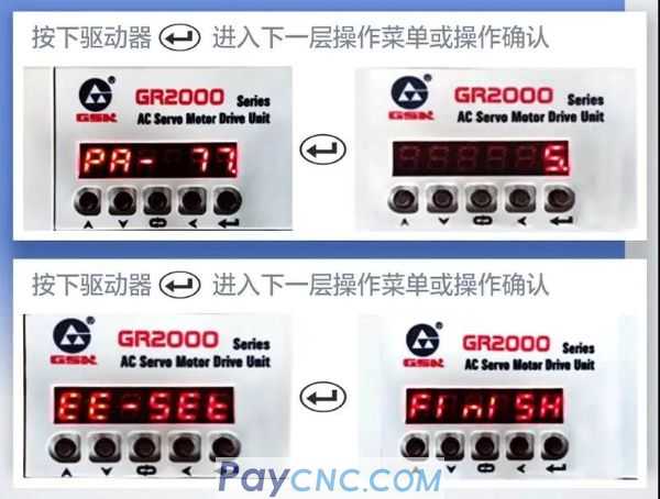
To complete resonance suppression, please modify PA77-5 and save it. Another purpose is to turn off the real-time detection frequency function to save program running time. In the 988TA system X axis as an example operation process
System-GSKLink-servo-servo parameters-X axis-modify the serial number 077 data to 5-save parameters
It can also be operated directly in the drive
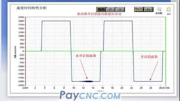
Comparison diagram before and after turning on the notch function of the CNC system measurement and adjustment software
Precautions
Note: Do not modify the servo parameter serial number 077 data to 5 on the 988TA system or set PA77=5 on the drive. The servo unit will always perform real-time resonance frequency detection. Data calculation will consume a lot of servo resources, which will inevitably cause the performance of the servo unit to decrease .
04 Conclusion
The above are the parameters and usage steps involved in the notch function of the GR servo drive
|
 |
| Products Catalogue | Home | About Us | Retrofit | Download | News | Tech Support | Contact Us | |
|
|
|