1 Confirmation of the number of servo axes and related initialization parameters
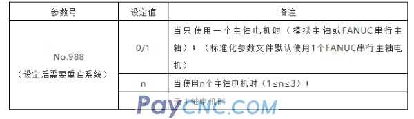
1) Confirm the values of parameter No.987 and No.988 according to the actual number of axes:
Press the picture, enter "987" on the MDI panel, and then search by number, confirm that the setting values of parameters No.987 and No.988 are consistent with the actual number of control axes, and then restart the system.
※: If the machine tool contains Cs axis, the setting value of parameter No.987 should include the number of Cs axis.
※: If No.987 and No.988 are 0, the M system defaults to 3 servos and 1 spindle, and the T series defaults to 2 servos and 1 spindle.
2) Servo motor code initialization:
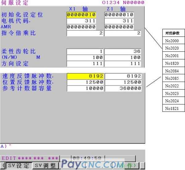
Set 3111#0 to display the servo setting screen.
Since the motor used in the standard parameter file may be different from the actual motor used by the NC user, the motor code must be reinitialized. The specific steps are as follows:
Put the system in MDI mode, press SYSTEM picture, press right again, press servo setting, press operation, press picture, press right, press switch, turn the page, you can see the following two parts of the screen:
After the parameter file is imported or the complete clearing is completed, the following parameters need to be adjusted manually:
Command multiplication ratio (CMR)=command unit/detection unit (range 1/2~48), setting value (No.1820)=CMR*2.
① "Initialization setting bit" is used to initialize the motor code, and "00000000" needs to be input during initialization;
※After the initialization is completed, the parameter will automatically change to "00000010"
② "Motor code", please fill in the corresponding motor code of each servo motor according to Appendix I: Servo Motor Code Table;
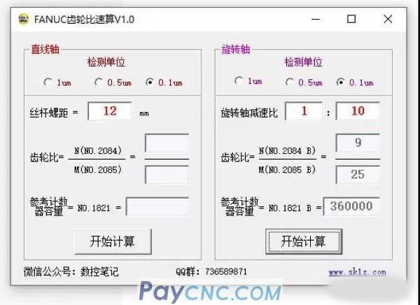
③ "Flexible gear ratio" N/M, its calculation formula is as follows:
N/M=The number of position pulses required for each revolution of the motor (converted to um)/1000000※
Setting example (1):
When the reduction ratio between the linear axis and the motor is 1:1, the pitch is 10mm/rev, and the detection unit is 1um
The number of pulses required for each rotation of the motor (10mm) is 10/0.001=10000 pulses
Then N/M=10000/1000000=1/100; set as shown in the figure above;
Setting example (2):
When the reduction ratio between the rotating shaft and the motor table is 10:1, and the detection unit is 1/1000 degrees
Each time the motor rotates, the worktable rotates 360/10 degrees. The number of position pulses per motor revolution is 360/10/(1/1000)=360000 pulses, then N/M=36000/1000000=9/ 250; set as shown in the figure above;
④ "Direction setting": If the actual running direction of the motor is opposite to the expected direction, the opposite number of the original data can be set: "111" or "-111";
⑤ "Reference counter capacity": the value of N before reduction in N/M;
※: The default machine tool is semi-closed loop. It is not suitable for the case of fully closed loop.
After inputting the above parameters according to the actual situation of the machine tool, especially after inputting "00000000" in the first line, please restart the NC;
After the system is powered on again, check the "Initialization Setting Bit" on the above page. If the value is "00000010", it means that the servo motor has been initialized.
2 Confirmation of the number of spindle axes and related initialization parameters
Spindle motor related parameters mainly include spindle motor type setting, spindle encoder type designation, initialization of motor related parameters, and spindle gear speed setting. Since the types and quantities of spindle motors used in the standard parameter file are different from the actual situation of the user, the following parameters must be confirmed, and manual adjustment is required after confirming the differences.
1) Confirmation and setting of the number of spindles
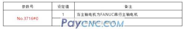
2) Confirmation and setting of the type of spindle motor
3) Confirmation and setting of the number of spindle amplifiers
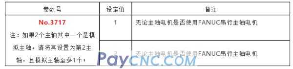
4) If you use FANUC's spindle motor, you can initialize the spindle motor as follows:
I. Press the SYSTEM key to enter the parameter screen, use the MDI panel to input "4133", press search, and find the corresponding motor code in Appendix II "Spindle Motor Code Table" according to the actual motor used, and press the imput key to fill in the parameter .
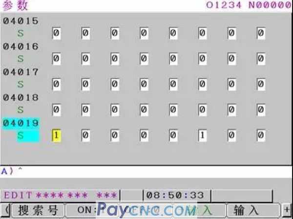
II. Press the SYSTEM key to enter the parameter screen, use the MDI panel to input "4019", press search, set parameter No.4019#7 to 1, as shown in Figure 2-2, and then cut off the NC and amplifier power.
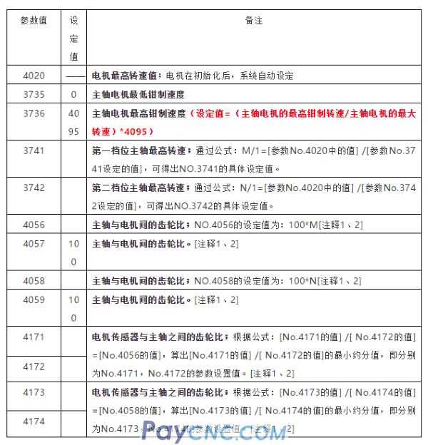
5) Confirmation and setting of parameters related to spindle speed
The standard parameter file is set up in a 1:1 direct connection between the motor and the spindle.
Conditions that need to be modified: If there is a reduction ratio between the spindle motor and the spindle, or there are 2 gears (or several gears), the gear ratios between them are M:1 reduction ratio (the first gear reduction ratio, the motor rotates M times , The spindle rotates once) and N:1 (the second gear reduction ratio), set according to the following table.
Note 1: When setting the parameters of multiple gears of the spindle, it is necessary to select through the combination of CTH1A and CTH2A signals. When the spindle has two gears, high and low, to match the parameter settings shown in the table above, the two signals CTH1A and CTH2A can be processed as follows: when the spindle is in the first gear, CTH1A=0, CTH2A=0; In the second gear, CTH1A=1, CTH2A=0 (other combinations correspond to different parameters, and the usage is exactly the same).
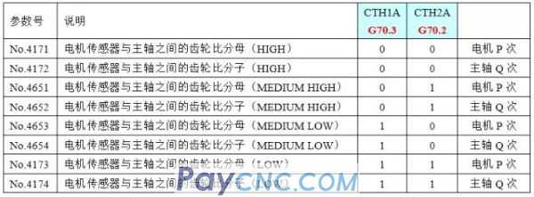
Note 2: Parameters No.4056~4059 and No.4171~4174 in the above table are setting examples when two gears are used, and the reduction ratio coefficients M and N are used when integers. For the use of 3 or 4 gears, please refer to the following parameter descriptions for setting.
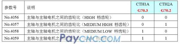
No. 4056~4059 are used to set the gear ratio between the spindle and the spindle motor. For example, when the spindle rotates once and the motor rotates 2.5 times, please set 2.5*100=250 for this parameter. The use of parameters is selected by the input signals CTH1A (G70.3) and CTH2A (G70.2). The gear and gear coupling state should correspond to the input signals CTH1A (G70.3) and CTH2A (G70.2).
Setting description:
1) No.4171~4174, No.4651~No.4654 are used to set any gear ratio between the motor sensor and the spindle. example:
If when the motor shaft rotates P times, the spindle rotates Q times (P, Q are integers without common divisors), the setting value is:
No.4171=P, No.4172=Q (assuming that CTH1A=0, CTH2A=0 at this time)
2) Special instructions:
When No.4651=0 or No.4652=0, the MEDIUM HIGH gear (CTH1A=0, CTH2A=1) is regarded as the same setting value as the HIGH gear (CTH1A=0, CTH2A=0).
When No.4653=0 or No.4654=0, the MEDIUM LOW file (CTH1A=1, CTH2A=0) is regarded as the same as the LOW file (CTH1A=1, CTH2A=1).
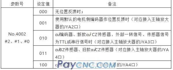
6) Modification of the spindle encoder type:
No.4002#2, #1, #0: Please set the type of spindle side detector as shown in the table below
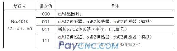
7) Modification of the encoder type of the spindle motor
No.4010#2, #1, #0:
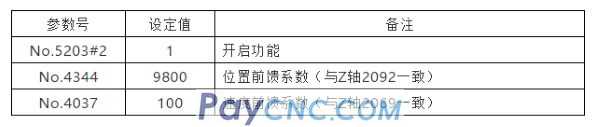
8) Default setting of feedforward parameters for spindle rigid tapping
 |
 |
| Products Catalogue | Home | About Us | Retrofit | Download | News | Tech Support | Contact Us | |
|
|
|