In fact, the answer is very simple in three steps:
Step 1: Open the refrigerator door
Step 2: stuff the elephant in
Step 3: Close the refrigerator door
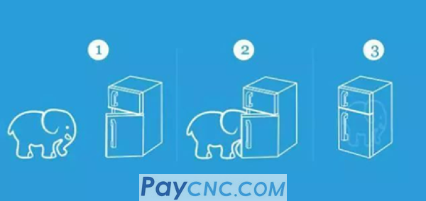
Although it is a joke of brain teasers, in theory, the above three steps can put the elephant in the refrigerator.
How did you put the elephant in the refrigerator?
The answer is: decomposition method
There is nothing difficult in the world, as long as you are willing to resolve it
I have practiced these two sentences for many years. When I wrote the craft many years ago, I used this technique to decompose the product drawing into the process drawing. I will determine how to clamp each process, what tools and measuring tools to use, etc. , Thereby forming a process file.
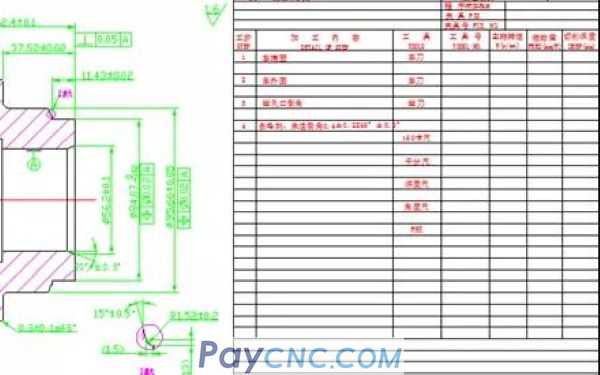
With this process file, it is much easier for the workshop to organize the production and processing of parts, just follow the process file.
In the past few years, I have been sharing the dry stuff of CNC programming, and from time to time I am playing with the powerful "decomposition method". Today, I will share some of the results with you, hoping to inspire you.
The two steps of the decomposition method:
The first step: firmly establish a thought that there is nothing difficult in the world, as long as you are willing to resolve it
Step 2: Start breaking down the matter
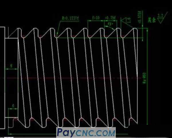
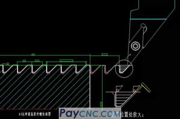
Give an example of a serrated thread, the diagram is as follows: (0-45° serrated thread)
Description:
Serrated threads also have angles of 0°, 3°, 7° and foreign countries 14.5°, 45°. There is currently no standard turning tool for turning such serrated threads. However, processing with a non-standard forming tool to a certain depth will generate a large cutting force, and will cause vibration during the cutting process, tool chipping, and tool breakage. How to solve it?
The method is as follows:
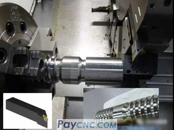
1. The choice of tool
Choose standard copy turning tools. For example (VBMT) standard tool with 35° included angle.
Tool bar model: SVJBL2525M 16
Blade model: VBMT160404……
2. Edit the program (start to decompose)
The first step: firmly establish a thought that there is nothing difficult in the world, as long as you are willing to resolve it
Step 2: Start breaking down the matter
As shown in the figure above, the tool cuts a layer of depth in the X direction, "steps" in the Z direction until it reaches the left side, and then continues to descend a certain depth in the Z direction, "steps" in the Z direction, and turns to the left side.
The specific decomposition is divided into two parts:
1. X-direction "layering" (solve whether the thread height is cut to the depth)
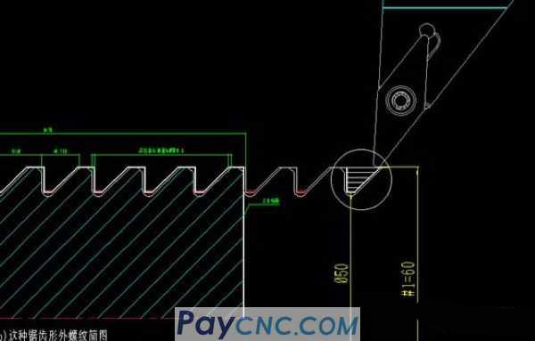
The diagram above: If the variable #1=60 is set to represent the outer diameter of the workpiece, it must be machined to D50 (small diameter of the thread)
Decompose two small problems:
①How to realize layering?
Answer: The variable is decremented #1=#1-2, that is, the initial value of #1=60 starts to decrement to the minor diameter of the thread 50
②How to control the depth of processing?
Answer: In conjunction with the IF...GOTO macro statement, a condition is set: If the value of #1 is greater than the value of the thread diameter, it means that the car is not finished, so jump back to continue the car.
2. "Stepping" in the Z direction (solve whether the tooth width is processed to size),
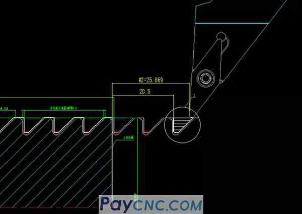
As shown in the above diagram, if the set variable #2=25.869 is the starting point of the thread (Z-direction) cycle, turn to Z=20.5 (leave 0.5mm margin on both sides and sides, that is, the width of coarse turning tooth: 5.369mm)
Description:
① The above figure #2=25.869 is the distance from the right side of the serrated thread to the end face of the workpiece
② Figure 20.5 above is the distance from the left side of the serrated thread to the end face of the workpiece
Break down two small issues:
1. How to achieve Z-direction "borrowing knife" stratification?
Answer: The decrement of the variable, namely #2=#2-1 (Note: The decrement of #2 has a corresponding relationship with #1, because the hypotenuse is 45 degrees. If the Z direction borrows the knife to move 1mm, the diameter X direction is 2mm ).
2. How to control the processing depth?
Answer: In conjunction with the IF...GOTO macro statement, a condition is set: if the value of #2 is larger or greater than 20.5, it means that the thread has not been turned to the left side, so jump back and continue.
Is it simple? It is exactly the same as the above X-layered program, and thus completed the borrowing in the Z direction. At this point in the analysis, if you have a clearer mind, I will directly go to the program, as follows:
%
O1; (Macro program for rough machining of 0°, 45° positive zigzag external thread-micro X: sosweetmum)
N01 #1=60;
N02 #2=25.869;
N03 #3=#2; (register the current value of #2 in #3)
N04 G54 S600 M03; (Set coordinate system, specify spindle speed, spindle forward)
N05 T0101; (tool location number and tool compensation number)
N06 G00 X150 Z200; (rapidly reach the total starting point)
N07 #2=#2-1; (Calculate the Z command value of the first cut of the layer to be turned)
N08 #1=#1-2; (Calculate the X command value of adding the first cut before the first cut of the layer to be turned)
N19 G00 X120; (knife lift)
N20 G00 Z#2; (Arrival at the starting point of the small thread cycle of turning this cut)
N21 X#1; (Arrival at the starting point of turning this thread)
N22 G32 Z-78 F10; (a knife in this layer of the car)
N23 G00 X120; (knife lift)
N24 #2=#2-0.3; (Calculate the Z command value of the next cut on this layer of the car)
N25 IF[#2 GT 20.5] GOTO 20; (the following stroke will go back to the left edge of the rough car to continue)
N26 Z20.5; (Z-direction position of the starting point of the last cut in the Z-direction arrival car)
N27 X#1; (Arrive at the starting point of the last cut in this layer of the car)
N28 G32 Z-78 F10; (the last cut in this layer of the car)
N29 G00 X120; (knife lift)
N30 #3=#3-1; (Calculate the Z command value of the first cut of the next layer, and it still exists in #3)
N31 #2=#3; (change the Z command value of the first cut of the next layer from #3 test to #2)
N32 IF[#1 GT 50] GOTO 07; (If this layer of the car has not reached the last floor, go back and continue the car)
N33 G00 X150 Z200; (Quickly return to the starting and retreating points)
N34 M05; (Spindle stopped)
N35 M30; (end of program)
%
|
 |
| Products Catalogue | Home | About Us | Retrofit | Download | News | Tech Support | Contact Us | |
|
|
|