Everyone knows how to draw electrical diagrams with AutoCAD (hereinafter referred to as CAD), but if you want to draw beautiful diagrams, you need to look at the following methods.
(1) About the background color, line, grid and capture function of CAD
The background color is white.
The line is a polyline, and the line width is set to 0.25. Know why? ISO stipulates in the drawing standard that all icons must be multiples of 2.5. The multiple here can be an integer or a decimal, such as 0.5, 0.2, 0.1 and so on. So when I draw, I set the line width of the polyline to 0.25.
The grid is set to 1.25. Because all tiles must be multiples of 2.5, the grid is defined as half of 2.5.
The capture function is turned off.
(2) About the tiles
This is the most critical move.
Let's take a look at the picture block of the relay normally open contact, as follows:
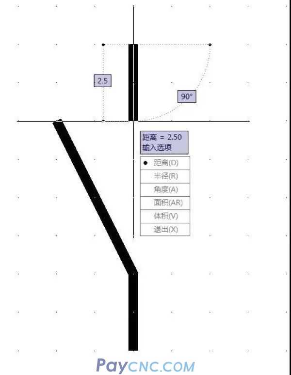
Note that the upper vertical line height is 2.5, the middle diagonal line height is 5, the lower vertical line height is 2.5, and the block width is also 2.5. The line width is of course 0.25.
The tiles can only be created by themselves. The more graphs are drawn, the more graph block libraries there are.
There are more tiles and complicated names. It is possible to modify the CAD menu and add a self-created menu specially used for recalling and inserting blocks by name, which is much more convenient.
(3) Drawing with blocks
The following figure is a combination block, which is a combination diagram of a low-voltage circuit breaker:
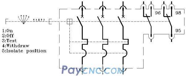
Note, when drawing a combination chart, be sure to always notice that all the spacings are multiples of 2.5. This is the key! Otherwise, the points and lines will not be aligned and misaligned.
I use blocks and combination blocks to form a control principle diagram of the direct start of the motor, as follows:

This picture has no special features. We frame it appropriately and highlight it as follows:

Does it feel different? We can use it to make some kind of emphasis.
Note: The color is mainly light cyan and green, which is very elegant. This is what I learned from Schneider. The documents made by Schneider have a very good visual effect. I found that they like to use pale colors to fill in the blanks.
Let's look at the picture below:
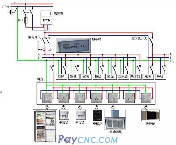
This is a diagram of the home power distribution system. We also frame it to see the effect:
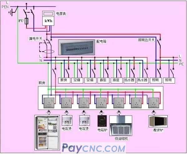
A little warm effect. However, the color seems to be darker, lighter is better.
In short, the drawing must be beautiful in order to achieve an eye-catching effect.
This is the block of the time-current characteristic curve coordinate diagram of the circuit breaker pre-saved in my gallery. Once needed, call it up immediately, and then use the attribute block to automatically draw the protection parameter curve. The characteristic curve of the circuit breaker LSI protection parameter has been drawn in the figure below:
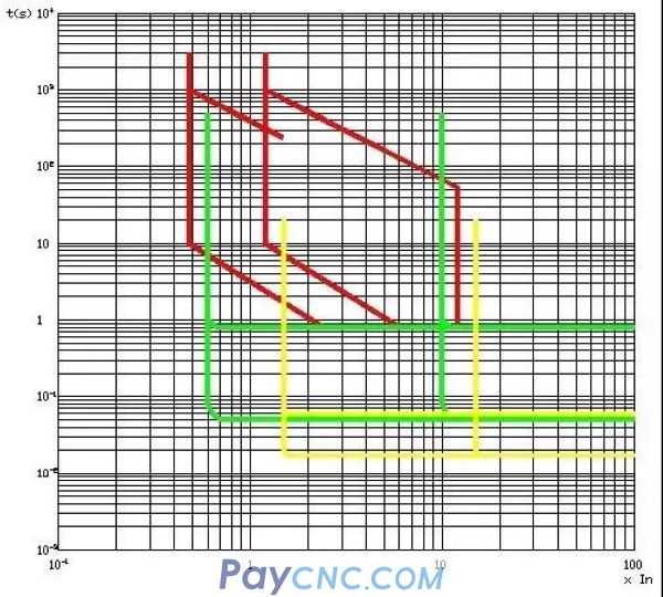
If the attribute block is directly written with text, the time-current characteristic curve of the circuit breaker release can be obtained immediately. In fact, the time I took to draw this graph was one and a half minutes.
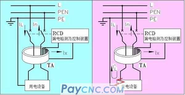
The figure below is what I use to illustrate the working principle of RCD.
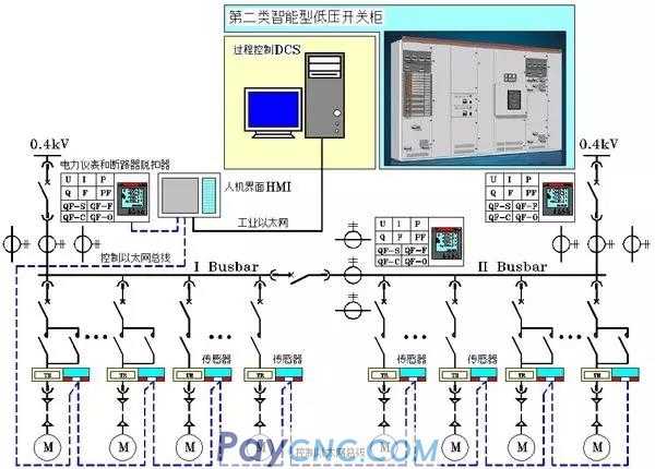
Finally, let me show you the diagrams in my manuscript that illustrate the smart switchgear:
Drawing with CAD is actually a technique. The more familiar the CAD is, the more convenience it provides.
Let me show you my home improvement design:
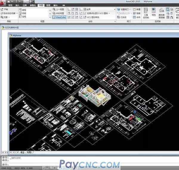
There are floor plans, layout plans, piping diagrams for electrical, water, gas, etc., as well as furniture structure diagrams and three views, as well as all home improvement materials. In other words, the decoration company only needs to construct according to my drawings. In this way, can the decoration company lie to me?
The following picture is a three-dimensional diagram of the core area, which is the center position of the picture above:
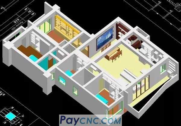
This picture is a real CAD three-dimensional picture, it can be viewed from any position and angle.
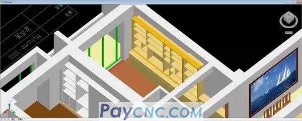
This is the bookcase of the study and the dining room part:
Drawing drawings is really a personal skill. Only by mastering this skill can you achieve complete freedom in expression.
|
 |
| Products Catalogue | Home | About Us | Retrofit | Download | News | Tech Support | Contact Us | |
|
|
|