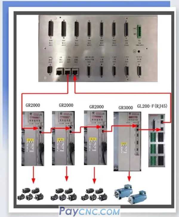
  Note: This figure takes the I / O unit GL200 (RJ45) as an example. The loop is the system bus 1 (XS11) out, after driving or I / O, and then back to the system bus 2 (XS12). 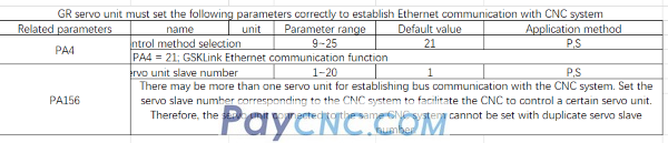
Note: When equipped with three drives, the value of PA156 should be set to 1, 2, 3 respectively, in no particular order;
When equipped with four drives, the value of PA156 should be set to 1, 2, 3, 4 respectively, in no particular order, and so on.
System parameters
[System]-[Parameter]-[Bit Parameter]-[0.0] Set 1 to select the bus;
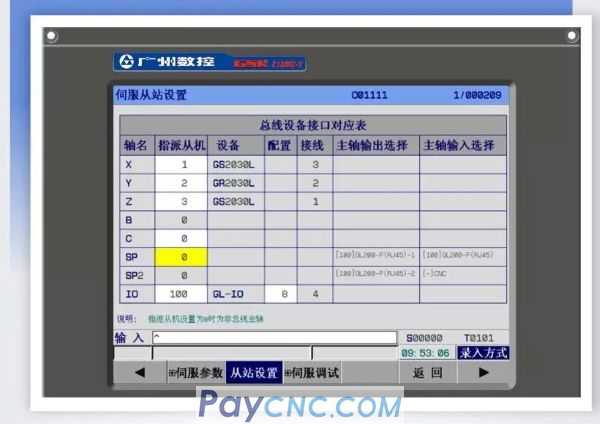
The setting value of the XYZ axis set by the slave in the bus configuration (assigned slave) corresponds to the driver PA156.
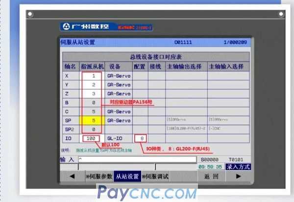
Note: The assigned slaves set by the slaves in the bus configuration. Set directly on the interface above; the IO configuration number can be selected according to the input to select different IO.
With GR3000 bus servo spindle
The first spindle slave SP (designated slave) is set to 5, which corresponds to the PA156 number of the GR3000 drive.
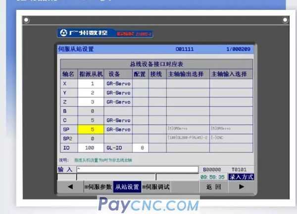
With non-bus servo spindle or ordinary frequency conversion spindle
The first spindle slave SP (assigned slave) is set to 0, and the spindle drive communication line is connected to the XS23 interface on the back of the system.
02 System and GE drive connection (bus type)
Description with GE + IO + GS3000 spindle
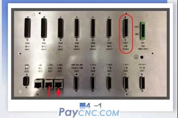
If a GE drive is connected, the system bus 1 (XS11) is connected to CN5, after the drive or I / O, and then to the system bus 2 (XS12) via CN4. The connection between the drive and the drive is the same as the GR drive connection. When equipped with three drives, the value of PA156 should be set to 123, in no particular order. When equipped with four drives, the value of PA156 should be set to 1234, in no particular order, and so on.
The spindle drive communication line is directly connected to the XS23 interface on the back of the system, as shown in Figure 4-1 below:
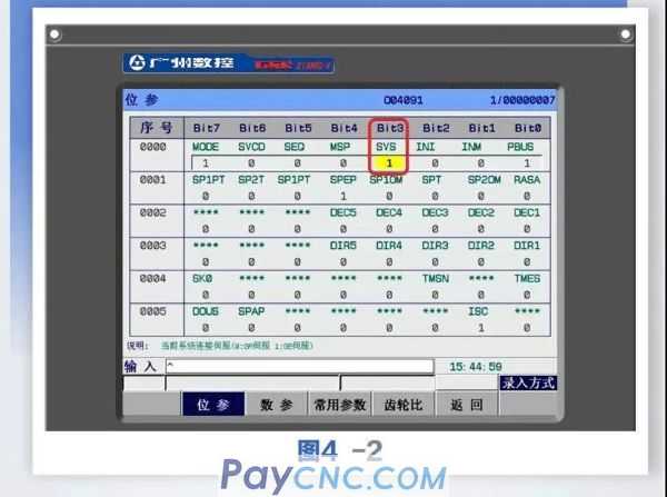
parameter settings
Press the system key to enter the system interface, press the corresponding + parameter] soft key to enter the parameter interface, set the search bit parameter 0 # 3 to 1, and then restart, as shown in Figure 4-2:
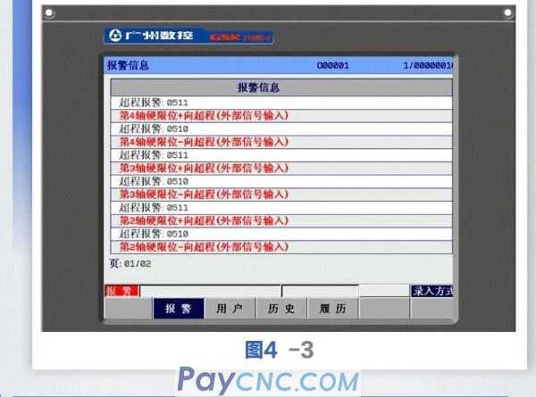
03Common alarms at initial power-on
Power on for the first time after normal communication. If no external hardware limit is connected, an alarm will appear, as shown in Figure 4-3
 Press the system key to enter the system interface, press the corresponding + parameter] soft key to enter the parameter interface, the search bit parameter 61 # 6 is set to 1, reset can be eliminated, as shown in Figure 4-4 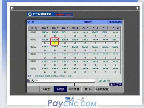 |
 |
| Products Catalogue | Home | About Us | Retrofit | Download | News | Tech Support | Contact Us | |
|
|
|