 The following describes the spindle adjustment method of the GSK218MC system in detail:
01 Commissioning of the spindle elastic knife
The mode of the 218MC spindle tensioning knife is a jog holding type. Press the switch to keep the loosening knife, and press it again to turn off.
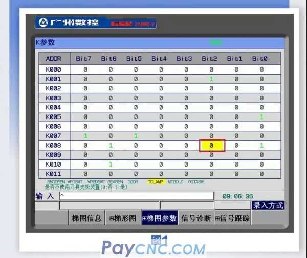
When using the elastic knife device, you need to modify K8.2 to 0, as shown in Figure 1. When using the tool magazine (K1.0 is 1), regardless of whether K8.2 is set or not, it is considered that the tool release device is used.
Use an external switch or use the buttons on the system operation panel. Only one of these two switches can be selected, and they cannot be used at the same time.
02 Debugging the spindle forward and reverse movements (the GR3000 series default parameters are sufficient).
03 Spindle speed adjustment
When there is a certain reduction ratio between the spindle motor and the spindle, the relationship between the analog voltage and the maximum speed is set through the proportional relationship, so as to achieve the same effect of setting the gear ratio.
The maximum speed corresponding voltage is set on the system side:
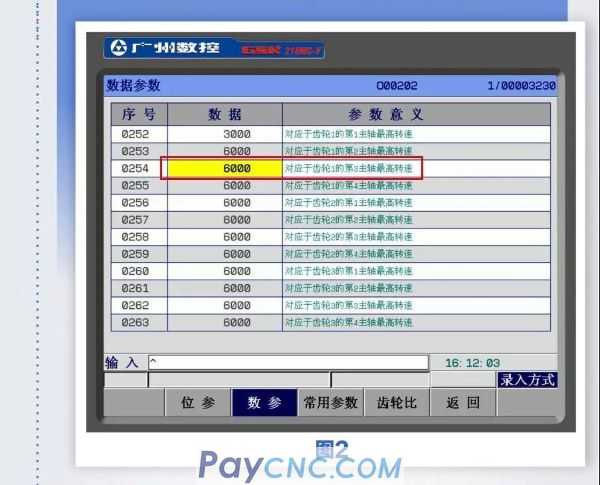
Set the parameter No. P254 for the highest speed corresponding to the gear 1 on the system side,
For example, set to 6000, the system outputs 10V voltage when S6000 is executed,
When executing S600, output 1V voltage, proportional output, as shown in Figure 2:
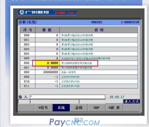
The analog voltage value of the spindle output on the system side is monitored in real time in the parameter 007 of [Diagnosis] [System], as shown in Figure 3.
The voltage should be set when the maximum speed is set on the system side:
Set the parameter No. P254 for the highest speed corresponding to the gear 1 on the system side,
For example, set to 6000, the system outputs 10V voltage when S6000 is executed,
When executing S600, output 1V voltage, proportional output, as shown in Figure 2:
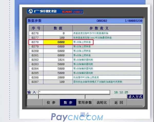
Maximum speed limit
System side: Number parameter P278, as shown in Figure 4.
Servo drive GS3000: PA54
Servo drive GS3000: PA54
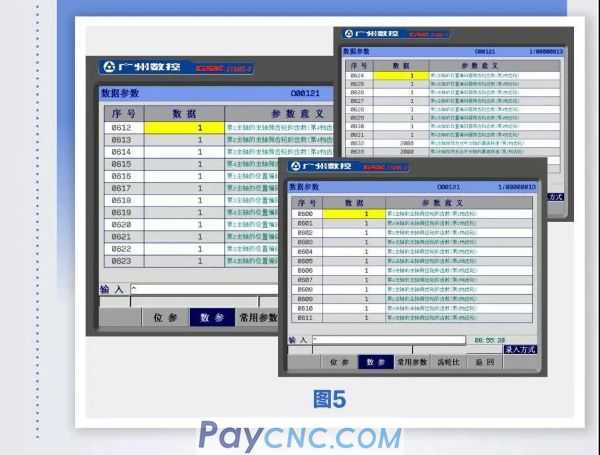
04 Gear ratio setting of spindle feedback
Setting method: The encoder feedback gear ratio reads the digital parameters P600 ~ P631, which is set by the customer according to the actual encoder gear ratio, as shown in Figure 5;
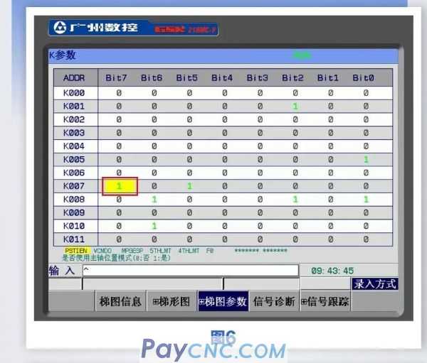
05 Rigid tapping
Steps to open the rigid tapping function:
Set K parameter K7.7 to 1, as shown in Figure 6;
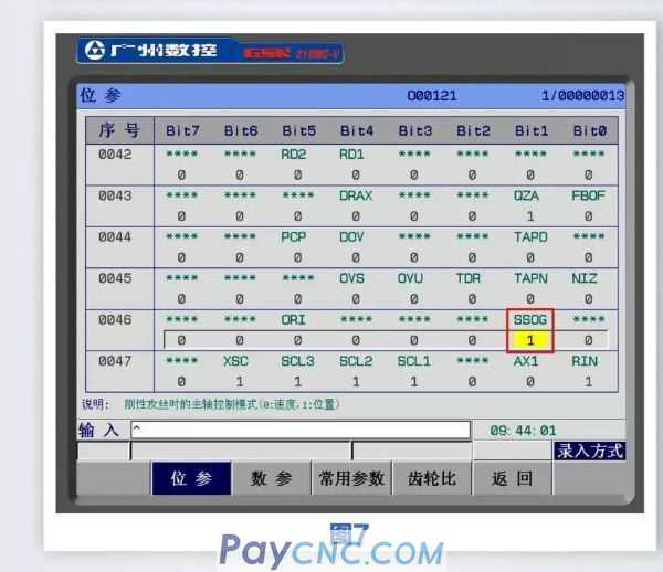
Set bit parameter 46 # 1 to 1, as shown in Figure 7;
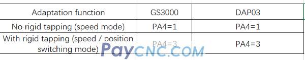
Set the spindle drive parameters: GS3000S set PA4 = 3, need to save;
When the direction of rotation of the rigid tapping is incorrect, modify the drive parameters to correct: GR3000 spindle drive reverses PA28, GS3000 reverses PA28, and needs to be saved.
  |
 |
| Products Catalogue | Home | About Us | Retrofit | Download | News | Tech Support | Contact Us | |
|
|
|