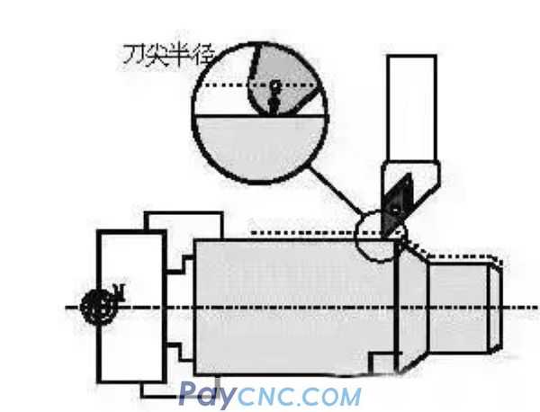
 The intersection of the main cutting edge and the secondary cutting edge will form a corner fillet. As shown below: 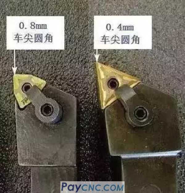
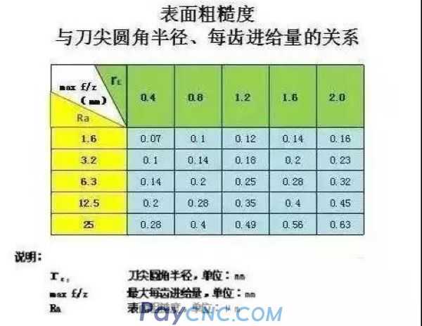
The corner radius of the turning tool directly affects the finish of the machined surface. The larger the radius, the smoother the surface. As shown in the following table:
However, if the radius is too large, chattering will occur due to the large contact between the tool and the workpiece. On the contrary, if the radius is too small, the tool tip will become weaker and wear quickly. Need to re-sharp frequently. The fillet radius is generally 0.3~0.4mm.
When machining on a CNC lathe, the fillet radius needs to be compensated.
When programming, the tool tip of the turning tool is usually considered as a point, but in fact there are rounded corners at the tool tip. When the program compiled according to the theoretical tool point point is used to process the surface parallel or perpendicular to the axis, such as the end face, the outer diameter, and the inner diameter, no error will occur. However, when chamfering, taper and arc cutting, there will be less or overcutting, as shown in the figure.
The CNC system with the function of automatic compensation of the tool nose arc can calculate the compensation amount according to the radius of the tool nose arc to avoid the occurrence of undercutting or overcutting.
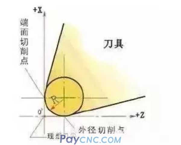
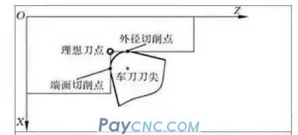
1) Turn the end face and inner and outer cylindrical faces. The following figure shows a tool tip with an arc and its orientation. The tool nose point used for programming and tool setting is the ideal tool nose point. Due to the existence of the tool nose arc, the actual cutting point is the tangent point between the tool nose arc and the cutting surface. When turning the end face, the actual cutting point of the tool nose arc is the same as the Z coordinate of the ideal tool nose point; when turning the outer circular surface and the inner hole, the actual cutting point is the same as the X coordinate value of the ideal tool nose point. Therefore, when turning the end face and the inner and outer cylindrical surfaces, it is not necessary to perform tool nose radius compensation.
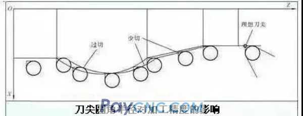
2) Turning taper and arc surfaces. When processing taper and arc surfaces, that is, when the processing track is not parallel to the axis of the machine tool, there is a position deviation between the actual cutting point and the ideal tool tip point in the X and Z coordinate directions. The influence of tool nose arc radius on machining accuracy is shown in the figure below. If you program with the ideal tool tip point, there will be less or overcutting, resulting in machining errors. The larger the radius of the tool nose arc, the larger the machining error.
 |
 |
| Products Catalogue | Home | About Us | Retrofit | Download | News | Tech Support | Contact Us | |
|
|
|