The following takes CNC programming as an example to introduce an advanced way of thinking: reasoning
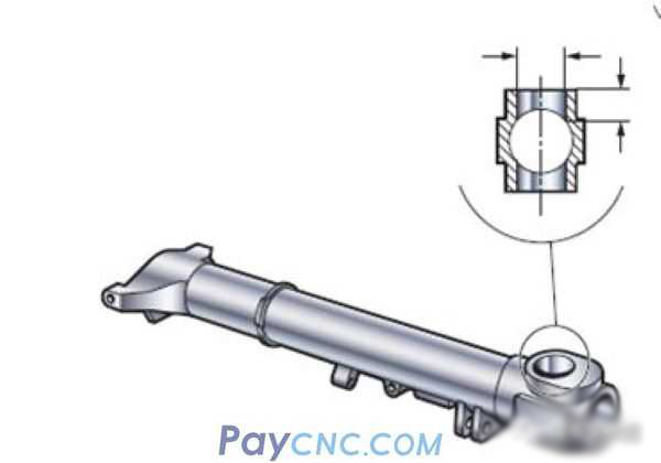
Just a few days ago, there was a master who wanted to process holes. He first thought of using drilling + boring. However, there are many types of holes and different specifications of drills and boring cutters are needed. The tool cost is too high. Considering the use of spiral interpolation to Milling instead of boring.
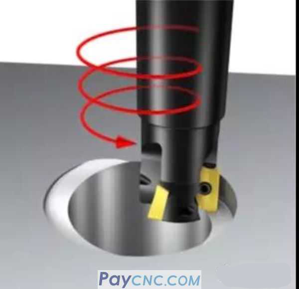
If you want to quickly compile a spiral interpolation milling program, you can directly apply the spiral parameter equation, and you can quickly complete the programming.
I shared this example many years ago, and today I will show you how to use reasoning to help you complete macro programming.
The core of reasoning is two words: relationship
For example: for the circle below, if point A is any point above the arc, the corresponding X and Y coordinates are as follows: (In a right-angled triangle, according to the Pythagorean theorem, the relationship between the angle θ and the side can be deduced The following relationship.
X=R*COSθ
Y= R*SINθ
This is exactly the parameter equation of the circle.
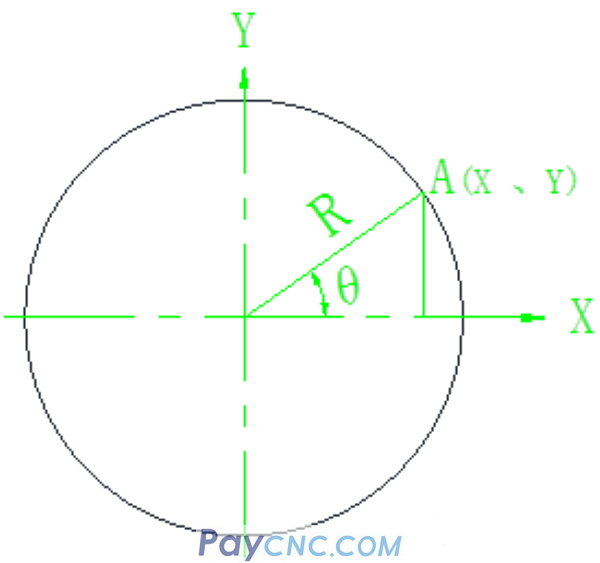
Because of the rotation of the included angle θ, an arc with a radius of R will be drawn.
This is a simple logical relationship. If the value of the included angle θ is different, then there will be a corresponding arc
such as:
θ is from 0 to 180, a semicircle can be drawn
θ is from 0 to 270, a 3/4 circle can be drawn
θ is from 0 to 360, a full circle can be drawn
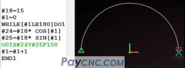
Therefore, #1 is set as self-increment, and the range of θ is from 0 to 180, which is the lower half circle.
The range of θ is from 0 to 360, which is a full circle below.
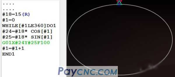
In the program:
#24=#18 * COS [#1]
#25=#18* SIN [#1]
It is the equation derived above, which uses the parameter equation of the circle to complete the programming of the circle.
So how to write the spiral interpolation program?
Imagine a question:
With the gradual increase of included angle variable #1, the value of the main axis Z direction also gradually changes with #1, isn’t it a spiral?
#1 self-increment (range 0~360) is a whole circle. The process of #1 self-increment also gradually changes the value in the Z direction. For example, set a variable #26 (representing the Z direction) and assign the value of #1 directly Give #26
That is: #26=#1
When #1=0, #26 is also equal to 0
When #1=1, #26 is also equal to 1.
When #1=360, #26 is also equal to 360
If you add a Z-#26 to G01X#24Y#25 in the above program, can a circle spiral be completed through XYZ three-axis linkage?
That is, while walking a full circle, Z dropped -360
If I want to walk a full circle, and the Z axis will drop by -1 at the same time, it is easy to derive a formula, that is, divide #1 by a coefficient of 360, as follows:
#26=#1/360
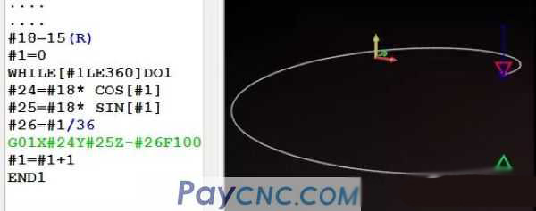
If you walk a full circle, the Z axis will drop by -10 at the same time? That is: #26=#1/36
Okay, I calculated a #26=#1/36 relational expression. It is exactly with the change of #1 that #26 also changes, and a circular spiral is completed through the XYZ three-axis linkage (Z drops 10mm per circle) The procedure is as follows:
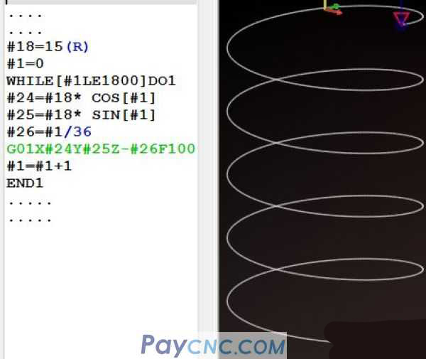
This is a circular spiral. If I want to mill 5 turns, then change the condition set in the WHILE statement: [#1LE 1800], (because one turn is 360 degrees, 5 turns is 360*5=1800)
The main program is as follows: (1 circle depth Z= -10, 5 circle depth Z=-50)
 |
 |
| Products Catalogue | Home | About Us | Retrofit | Download | News | Tech Support | Contact Us | |
|
|
|