Common structure size notation method
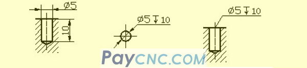
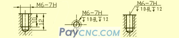
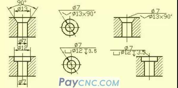
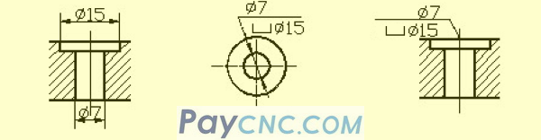
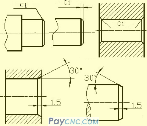
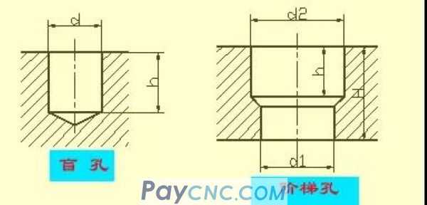
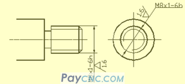
Common hole size injection method (blind hole, threaded hole, counterbore, countersink hole); chamfer size injection method.
2
Machining structure on parts
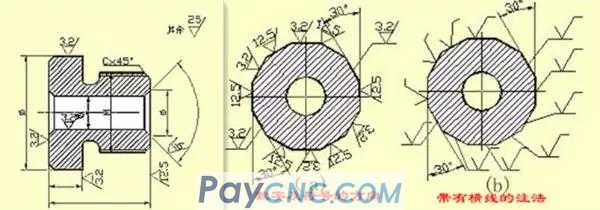
❖ Undercut and grinding wheel overtravel groove
When parts are cut, in order to facilitate the withdrawal of the tool and ensure that the contact surfaces of the relevant parts are close during assembly, the undercut groove or the grinding wheel overtravel groove should be pre-machined at the step of the processed surface.
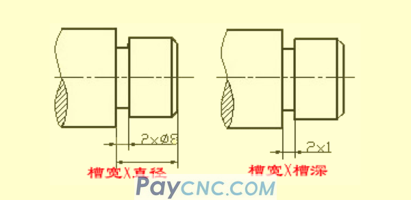
The size of the undercut when turning the outer circle can generally be marked in the way of "groove width × diameter" or "groove width × groove depth". Grinding wheel overtravel groove when grinding outer circle or grinding outer circle and end face.
Drilling structure
The blind hole drilled with a drill bit has a cone angle of 120° at the bottom. The drilling depth refers to the depth of the cylindrical part, excluding the cone pit. At the transition of the stepped drilling, there is also a cone angle of 120° round table, its drawing and size notation.
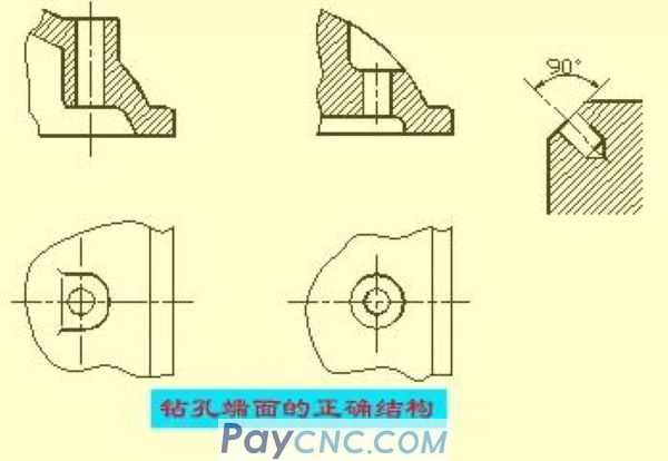
When drilling with a drill, it is required that the axis of the drill is as perpendicular to the end face of the drilled hole as possible to ensure the accuracy of the drilling and avoid the drill from breaking. The correct structure of the three drilling end faces.
Bosses and pits
The contact surface of a part with other parts is generally processed. In order to reduce the processing area and ensure good contact between the surfaces of the parts, bosses and pits are often designed on the castings. Bolted support surface boss or support surface recessed form; in order to reduce the processing area, a groove structure is made.
3
Common part structure
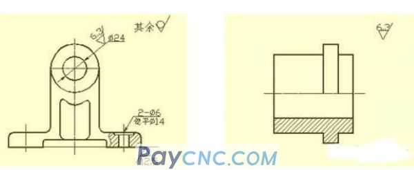
❖ Shaft sleeve parts
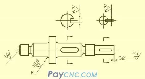
Such parts generally include shafts, bushings and other parts. When expressing the views, as long as you draw a basic view and add appropriate cross-sectional views and dimensions, you can express its main shape features and local structure. In order to facilitate the viewing of pictures during processing, the axis is generally placed horizontally for projection, and it is best to choose the position where the axis is the lateral vertical line.
When marking the size of bushing parts, its axis is often used as the radial size benchmark. From this, the Ф14 and Ф11 shown in the figure (see A-A section), etc. are noted. In this way, the design requirements and the process reference during processing (when the shaft parts are processed on the lathe, the center hole of the shaft is held by the thimble at both ends) is unified. The length direction datum often chooses important end faces, contact faces (shoulders) or machined faces.
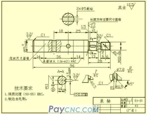
The right shoulder with a surface roughness of Ra6.3 as shown in the figure is selected as the main dimension reference in the length direction, from which dimensions such as 13, 28, 1.5 and 26.5 are injected; then the right shaft end is the length direction The auxiliary base of, thus marking the total length of the shaft 96.
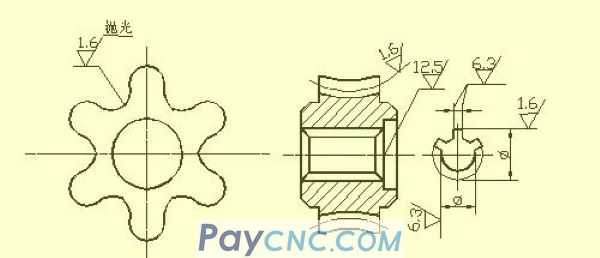
❖ Disc cover parts
The basic shape of this kind of parts is a flat disc, generally including end caps, valve caps, gears and other parts. Their main structure is basically a rotating body, usually with various shapes of flanges and uniformly distributed circular holes. And ribs and other local structures. When selecting a view, generally select the cross-sectional view of the symmetry plane or the axis of rotation as the front view, and also need to add appropriate other views (such as left view, right view or top view) to express the shape and uniform structure of the part. As shown in the figure, a left view is added to express a square flange with rounded corners and four uniformly distributed through holes.
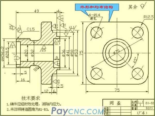
When marking the size of disc cover parts, the axis through the shaft hole is usually selected as the radial dimension reference, and the main dimension reference in the length direction is often the important end surface.
❖ Fork frame parts
Such parts generally include forks, connecting rods, bearings and other parts. Due to their variable processing positions, when choosing the main view, the main consideration is the working position and shape characteristics. For the selection of other views, two or more basic views are often required, and appropriate local views, cross-sectional views, etc. must be used to express the local structure of the part. The view shown in the footrest parts drawing is refined and clear. The right view is not necessary for expressing the width of the bearing and ribs. For T-shaped ribs, the cross-section is more appropriate.
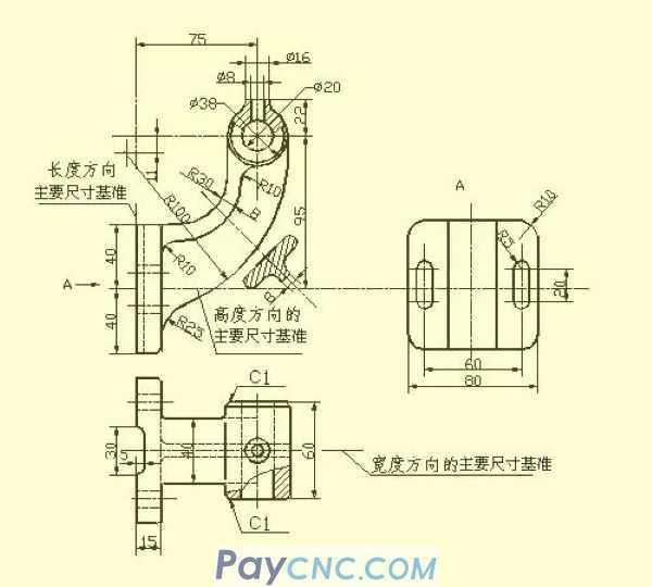
When marking the dimensions of fork bracket parts, the installation base surface or the symmetry plane of the part is usually selected as the dimension reference. Refer to the figure for the dimensioning method.
❖ Box parts
Generally speaking, the shape and structure of this type of parts are more complex than the previous three types of parts, and the processing position changes more. Such parts generally include valve body, pump body, reducer box and other parts. When choosing the main view, the working position and shape characteristics are mainly considered. When selecting other views, appropriate sectional views, cross-sections, partial views, and oblique views should be adopted according to the actual situation to clearly express the internal and external structure of the part.
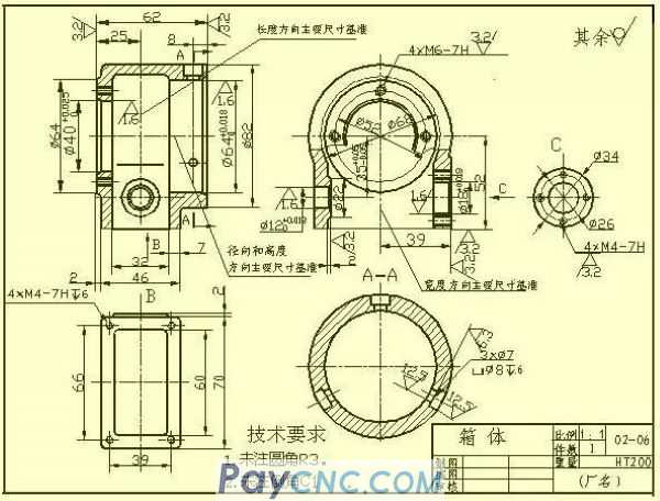
In terms of dimensioning, the axis, important installation surface, contact surface (or processing surface) required by the design, and the symmetry surface (width, length) of some main structures of the box are usually selected as the size benchmark. For the parts that need to be cut on the box, the dimensions should be marked as far as possible to facilitate processing and inspection.
4
Surface roughness
❖ The concept of surface roughness
The micro-geometric characteristics of the peaks and valleys with small spacing on the surface of the part are called surface roughness. This is mainly due to the tool marks left by the tool on the surface of the part and the plastic deformation of the surface metal during cutting.
The surface roughness of parts is also a technical index for evaluating the surface quality of parts. It has an impact on the mating properties, working accuracy, wear resistance, corrosion resistance, airtightness and appearance of the parts.
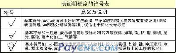
❖ The code, symbol and mark of surface roughness
GB/T 131-1993 specifies the surface roughness code and its notation. The symbols on the drawing that indicate the surface roughness of the parts are shown in the table below.
Main evaluation parameters of surface roughness
The evaluation parameters of part surface roughness are:
1) Contour arithmetic mean deviation (Ra)
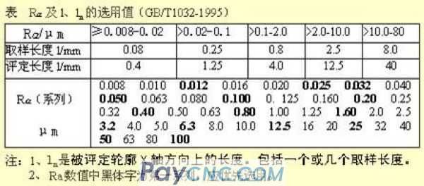
Within the sampling length, the arithmetic mean of the absolute value of the contour offset. See the table for the value of Ra and the sampling length l.
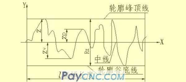
2) Maximum profile height (Rz)
The distance between the top line of the contour peak and the bottom line of the contour peak within the sampling length.
Note: The Ra parameter is preferred when using it.
❖ Marking requirements for surface roughness
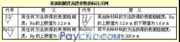
1) Example of surface roughness code marking
When the surface roughness height parameters Ra, Rz, and Ry are marked with numerical values in the code, except that the parameter code Ra can be omitted, the other parameters must be marked with the corresponding parameter code Rz or Ry before the parameter value. Refer to the table for marking examples.
2) The method of marking the numbers and symbols in the surface roughness of the surface roughness
Marking method of surface roughness symbols on drawings
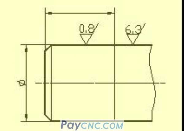
1) The surface roughness code (symbol) should generally be noted on the visible contour line, the boundary line or their extension, and the tip of the symbol must point from the outside of the material to the surface.
2) The direction of the numbers and symbols in the surface roughness code must be marked as required.
On the same drawing, each surface is generally marked with a code (symbol) only once, and as close as possible to the relevant dimension line. When the space is narrow or it is inconvenient to label, it can lead to the label. When all the surfaces of the part have the same surface roughness requirements, they can be uniformly marked on the upper right corner of the drawing. When most of the parts have the same surface roughness requirements, the code (symbol) that is used most can be used. Note at the same time in the upper right corner of the drawing, and add the words "the rest". The height of the uniformly marked surface roughness code (symbol) and explanatory text should be 1.4 times that of the drawing mark.
The surface roughness code (symbol) number of the continuous surface on the part, the surface of the repeated elements (such as holes, teeth, grooves, etc.) and the discontinuous surface connected by a thin solid line are only noted once.
When there are different surface roughness requirements on the same surface, use thin solid lines to draw the dividing line, and note the corresponding surface roughness code and size.
When the tooth (tooth) shape is not drawn on the working surface of gears, threads, etc., the surface roughness code (symbol) notation method is shown in the figure.
The working surface of the center hole, the working surface of the keyway, the surface roughness code of the chamfer, and the rounded corner can be simplified and marked.
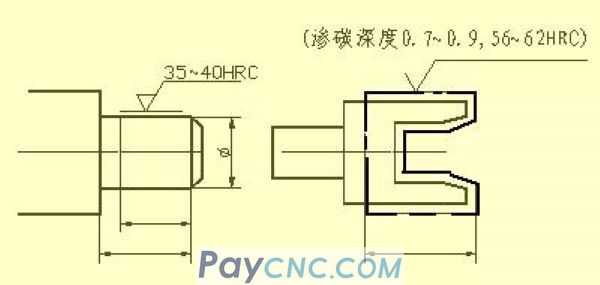
When the parts need to be partially heat-treated or partially plated (coated), thick dotted lines should be used to draw the range and mark the corresponding dimensions. The requirements can also be written on the horizontal line of the long side of the surface roughness symbol.
5
Standard tolerance and basic deviation
In order to facilitate production, realize the interchangeability of parts and meet different usage requirements, the national standard "Limits and Fits" stipulates that the tolerance zone is composed of two elements: standard tolerance and basic deviation. The standard tolerance determines the size of the tolerance zone, and the basic deviation determines the location of the tolerance zone.
1) Standard tolerance (IT)
The value of the standard tolerance is determined by the basic size and tolerance class. The tolerance level is a mark to determine the accuracy of the size. The standard tolerance is divided into 20 levels, namely IT01, IT0, IT1,..., IT18. The accuracy of its size decreases from IT01 to IT18. For the specific values of standard tolerances, see relevant standards.
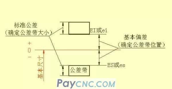
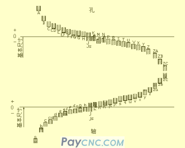
2) Basic deviation
The basic deviation refers to the upper or lower deviation of the tolerance zone relative to the zero line position in the standard limit and fit, generally refers to the deviation close to the zero line. When the tolerance zone is above the zero line, the basic deviation is the lower deviation; otherwise, it is the upper deviation. There are 28 basic deviations in total, and the code is expressed in Latin letters, with uppercase as hole and lowercase as shaft.
It can be seen from the series of basic deviations that: the basic deviation A~H of the hole and the basic deviation k~zc of the shaft are the lower deviation; the basic deviation K~ZC of the hole and the basic deviation a~h of the axis are the upper deviation, JS The tolerance zones of and js are symmetrically distributed on both sides of the zero line, and the upper and lower deviations of the hole and shaft are +IT/2 and -IT/2 respectively. The basic deviation series diagram only shows the position of the tolerance zone, not the size of the tolerance. Therefore, one end of the tolerance zone is an opening, and the other end of the opening is limited by the standard tolerance.
The basic deviation and standard tolerance have the following calculation formulas according to the definition of dimensional tolerance:
ES=EI+IT or EI=ES-IT
ei=es-IT or es=ei+IT
The tolerance zone code of the hole and shaft is composed of the basic deviation code and the tolerance zone grade code.
6
Cooperate
The relationship between the holes and the shaft tolerance zone that have the same basic size and are combined with each other is called a fit. According to the different requirements of use, the fit between the hole and the shaft is tight or loose, so the national standard stipulates the type of fit:
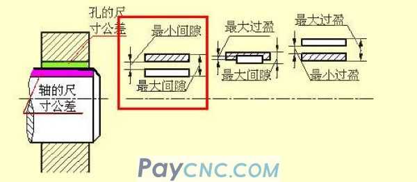
1) Clearance fit
When the hole is assembled with the shaft, there is a clearance (including the minimum clearance equal to zero). The tolerance zone of the hole is above the tolerance zone of the shaft.
2) Transition fit
When the hole is assembled with the shaft, there may be a clearance or interference fit. The tolerance zone of the hole and the tolerance zone of the shaft overlap each other.
3) Interference fit
When the hole is assembled with the shaft, there is an interference fit (including the minimum interference equal to zero). The tolerance zone of the hole is below the tolerance zone of the shaft.
Benchmark system
When manufacturing matching parts, one of the parts is used as the reference part, and its basic deviation is fixed. The system of obtaining various coordinations of different properties by changing the basic deviation of another non-reference part is called the reference system. According to the actual needs of production, the national standard stipulates two benchmark systems.
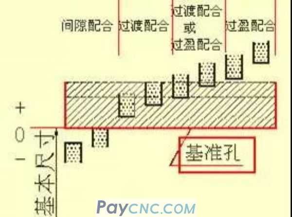
1) Basic hole system (as shown in the lower left picture)
Basic hole system-refers to a system in which the tolerance zone of a hole with a certain basic deviation and the tolerance zone of a shaft with different basic deviations form various coordination. See the picture below left. The hole made by the base hole is called the datum hole, its basic deviation code is H, and its lower deviation is zero.
2) Basic shaft system (as shown in the lower right picture)
Base shaft system--refers to a system in which the tolerance zone of the shaft with a certain basic deviation and the tolerance zone of the hole with different basic deviations form various coordination. See the picture below right. The axis of the basic axis system is called the reference axis, its basic deviation code is h, and its upper deviation is zero.
Match code
The matching code is composed of the tolerance zone code of the hole and the shaft, written in the form of a component number, the numerator is the tolerance zone code of the hole, and the denominator is the tolerance zone code of the shaft. Anything that contains H in the molecule is a basic pore system, and any that contains h in the denominator is a basic shaft system.
For example 1: φ25H7/g6 means that the basic size of the fit is φ25, the clearance fit of the base hole, the tolerance zone of the reference hole is H7, (the basic deviation is H tolerance level is 7), and the tolerance zone of the shaft is g6 (The basic deviation is g, and the tolerance level is 6).
For example 2: φ25N7/h6 means that the basic size of the fit is φ25, the basic shaft transition fit, the tolerance zone of the reference shaft is h6, (the basic deviation is h, the tolerance level is 6), and the tolerance zone of the hole is N7 (The basic deviation is N, and the tolerance level is 7).
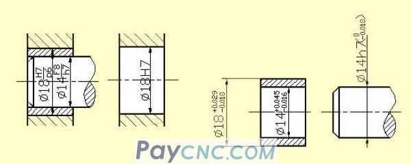
❖ Marking of tolerance and fit on the drawing
1) Mark the tolerance and fit on the assembly drawing, and use the combined injection method.
2) There are three ways of marking on the part drawing.
7
Geometric tolerance
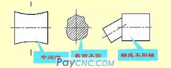
After the parts are processed, there are not only dimensional errors, but also geometrical shape and mutual position errors. Even when the size of the cylinder is qualified, it may have one end large, the other end small, or the middle thin and the two ends thick, etc., and its cross section may not be round, which is a shape error. For stepped shafts, different axes of each shaft section may appear after machining, which is a position error. Therefore, the shape tolerance refers to the allowable variation of the actual shape from the ideal shape. Position tolerance refers to the allowable variation of the actual position from the ideal position. Both are referred to as form tolerance.
 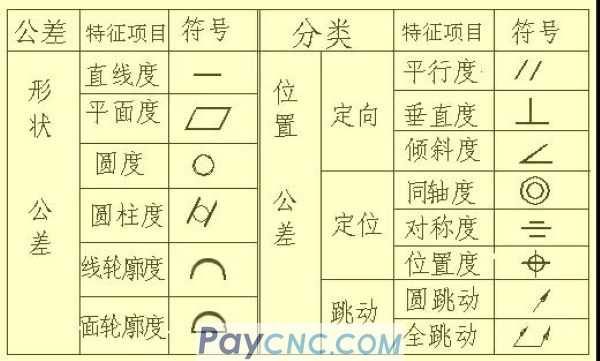
Code of shape and position tolerance
The national standard GB/T 1182-1996 stipulates that the shape and position tolerances shall be marked with codes. In actual production, when the geometric tolerance cannot be marked with a code, it is allowed to use text in the technical requirements.
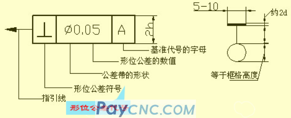
The shape and position tolerance codes include: each item of the shape and position tolerance symbols, the shape and position tolerance frame and guide line, the shape and position tolerance values and other related symbols, and the reference code, etc. The height h of the font in the frame is the same as the size number in the drawing.
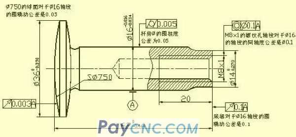
Example of Geometric Tolerance Marking
For a valve stem, the text added near the geometric tolerance marked in the figure is repeated for the reader's explanation, and there is no need to repeat the annotation in the actual drawing.
 |
 |
| Products Catalogue | Home | About Us | Retrofit | Download | News | Tech Support | Contact Us | |
|
|
|