no matter how:
Online measurement
Automatic control
Abrasive processing
Product processing
I can appreciate its convenience!
It's a bit vague to say so, I like to gather a little bit and take the specific examples in "Frame Programming 1.0" to illustrate.
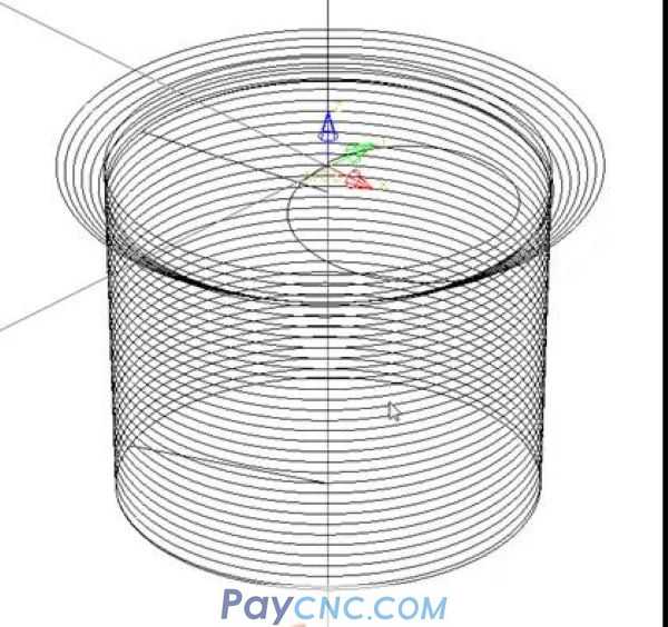
Example: Spiral milling of various inner cylindrical and inner conical surfaces
The following drawings
One, the choice of tool
Programming is inseparable from the selection of tools, even the software (CAM) also needs to create a specific tool.
There will be a problem:
For example, you use the D20R3 milling cutter to write a program, but the tool is occupied during production (or there is a problem with the tool during the cutting process, and a suitable tool needs to be replaced)
The program needs to be edited or modified again.
How to solve this problem?
I divided the milling cutters used for milling inner cylindrical and inner conical surfaces into three categories: (as shown in the figure below)
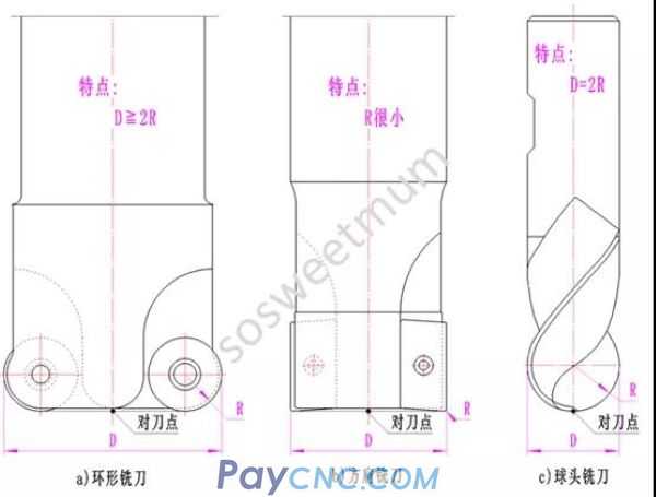
1. Annular milling cutter
2. Square shoulder milling cutter
3. Ball end milling cutter
Annular milling cutter (also called Niubi milling cutter) has two parameters: insert radius and turning diameter.
The shoulder milling cutter can be regarded as an annular milling cutter with a small blade radius.
The ball-end milling cutter can be regarded as an annular milling cutter with a turning radius twice the blade radius.
So only two variables need to be set when compiling a macro program:
1. Tool diameter D (#7)
2. Tool fillet R (#18)
In this way, when the on-site operator replaces the tool, the programmer does not need to edit (modify) the program again, but directly assign the corresponding variable!
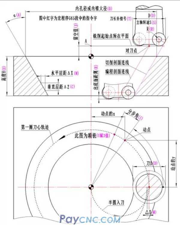
Two, programming
Using spiral milling and programming with the method of fitting spiral lines, our programming can do whatever:
(1) What size and cone angle of the inner conical surface to mill;
(2) What size of inner cylindrical surface to mill;
(3) What kind of milling cutter and what size milling cutter to use;
(4) Down milling or up milling is used;
(5) The milling cutter used has several teeth;
(6) How much feed is taken per tooth per revolution;
(7) What is the spindle speed?
(8) What is the length compensation number of the milling cutter?
(9) Is it rough milling or fine milling;
can do:
As long as the inner cylindrical surface and inner conical surface are milled, they can be processed by this general macro program.
Description:
The inner cylindrical surface can be regarded as an inner conical surface with a cone angle of zero degrees, so the processing of the inner conical surface can cover the processing of the inner cylindrical surface. (Set an angle variable only)
The procedure is as follows:
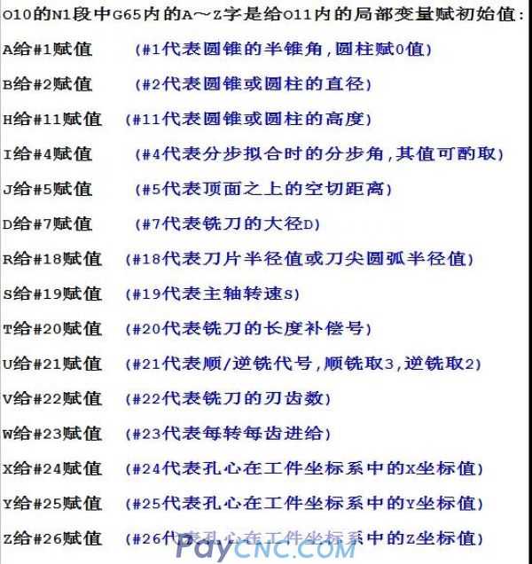
O10;
N1 G65 P11 Aa Bb Hh Cc Ii Jj Dd Rr Ss Tt Uu Vv Ww Xx Yy Zz; (call the O11 program and assign initial values to the variables)
N29 M05; (Spindle stopped)
N30 M30; (end of program)
Note:
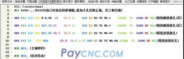
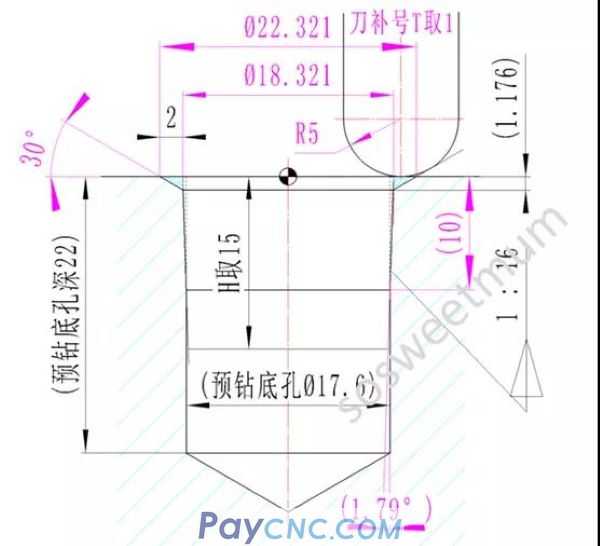
Application example 1: (as shown in the picture)
Continuous roughing and finishing milling a funnel-shaped inner hole (taper hole + straight hole)
The procedure is as follows:
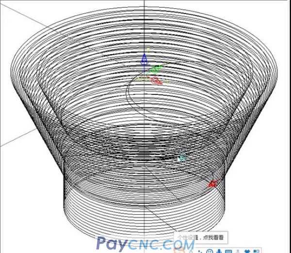
The tool path is shown in the figure below:
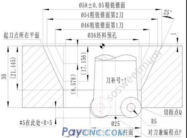
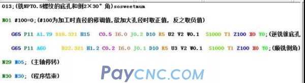
Application example 2: (as shown in the picture)
Continuously milling NPT0.5 threaded taper bottom hole and inverted threaded hole 30° angle
The procedure is as follows:
The tool path is shown in the figure below:
This is the generality of macro programs, everyone will experience it!
Because it is streamlined, efficient and versatile
CNC programming framework, program standard template, this is a super high gold content method
|
 |
| Products Catalogue | Home | About Us | Retrofit | Download | News | Tech Support | Contact Us | |
|
|
|