 The 218MC pitch error compensation adopts a more concise way. It only needs to determine the error compensation value of the positive movement end position of each compensation area and their corresponding compensation number. The following describes the pitch compensation debugging process in detail: 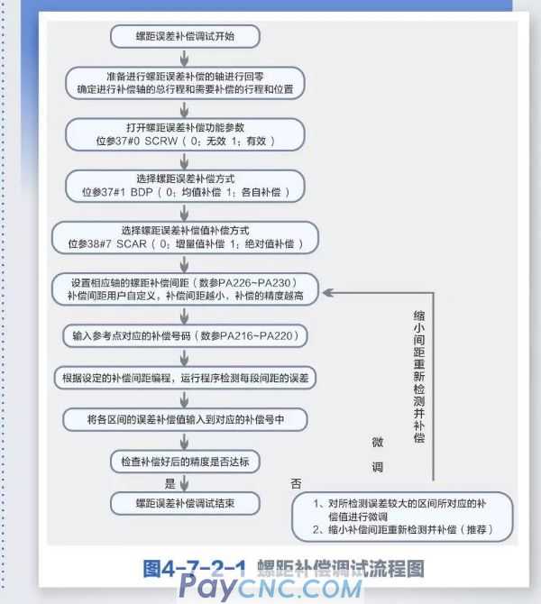
02Pitch compensation value input steps
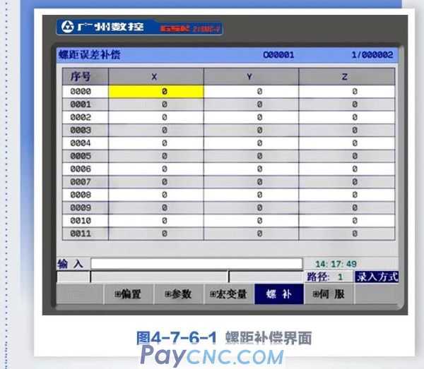
Press the system key to enter the system page. The page consists of five sub-interfaces: [+offset], [+parameter], [+macro variable], [pitch compensation], and [+servo]. Press the [pitch compensation] soft key to enter the pitch error The compensation page, as shown below:
Enter the compensation value of each axis directly, the steps are as follows:
Choose entry method;
Press the setup key, and then press the [Password] soft key to enter the [Settings (Password)] page, and enter the password for the system debugging level or above.
Press the [Settings] soft key to enter the [Settings] page and turn on the parameter switch
Press the system key, then press the [Pitch Compensation] soft key to enter the pitch error compensation display interface;
Use the up, down, left, and right direction keys to position the cursor to the target position, key in the compensation value, and press the enter key, the compensation value is entered and displayed.
03 Precautions for pitch error compensation setting
The set compensation amount is related to factors such as the positional relationship between the zero point and the compensation point, the direction of mechanical movement, and the compensation interval.
The compensation amount of the compensation number N (N=0,1,2,3...255) is determined by the mechanical error in the interval N~N1. The number of compensation numbers that can be set for each axis is 256.
Set the mechanical zero point as the compensation origin, and the compensation amount set for each axis as the parameter value.
Axes that can be compensated: X, Y, Z4th axis.
Compensation range: compensation value (-999 pulse equivalent to +999 pulse equivalent) * minimum compensation unit. (Metric system: 0.001deg)
The unit of pitch error compensation of the rotation axis is deg.
When the pitch error compensation interval is set to zero, the system will not compensate
(Pitch error compensation is to compensate the pitch error near the middle point of the compensation interval)
After setting the relevant parameters of the pitch error compensation, it needs to be powered off and restarted to take effect after the mechanical zero return.
After pitch compensation, the mechanical zero point of the machine tool cannot be changed at will, because after the mechanical zero point position is changed, the position of the pitch compensation point will not match the actual compensation position of the machine tool, resulting in a decrease in the accuracy of the machine tool. If you need to reset the mechanical zero point for special reasons, you need to recheck the pitch error compensation data at this time.
Setting the pitch error compensation data can compensate the pitch error of each axis, so as to achieve the purpose of improving the accuracy of the machine tool. The unit of the compensation value is the detection unit. Different machine tools have different pitch errors, so the compensated data is different. The pitch compensation data should be set according to the machine characteristics after the machine is connected to the CNC system. After the pitch error compensation data is set, in principle, the end user cannot change these data, because changing these data will reduce the accuracy of the machine tool.
04 Conclusion
Through the above description, you can quickly understand the five ways of position page display, and effectively provide an intuitive and concise display interface. The pitch compensation number of the 218MC system is 0—255.218MC. The concept of compensation points is omitted. The number of compensation points = lead screw stroke/compensation distance" is derived. The user only needs to determine the number of compensation points or the compensation distance according to the needs, and the other parameter can be determined by the lead screw stroke to ensure stable processing and debugging.
|
 |
| Products Catalogue | Home | About Us | Retrofit | Download | News | Tech Support | Contact Us | |
|
|
|