 GSK988TA machine tool numerical control system GSKLink1 bus connection, adopts serial spindle control mode, all signals are sent to the driver through the bus. When adding a power head, it is necessary to configure this tapping GR driver. Adding the power head function can perform drilling, milling and side tapping to form a turning center machine tool.
Set the current operation authority to the machine manufacturer level, and the password is 222222. During the debugging and setting process, the corresponding options of the cursor moving tool will have corresponding comments.
01 First power function debugging
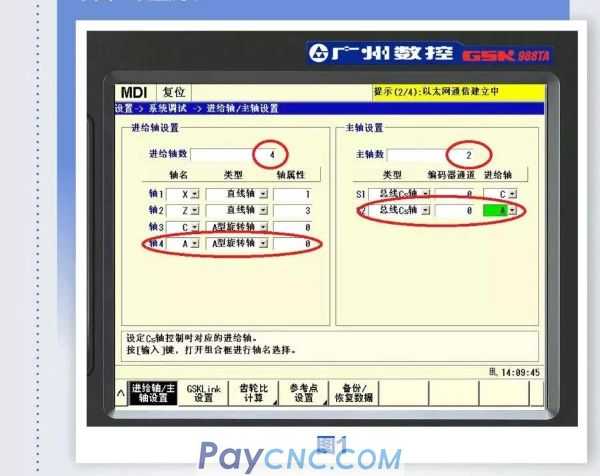
[Settings]-[System debugging], enter "Feed axis/spindle setting" and set it as shown in Figure 1.
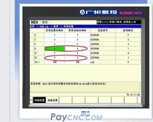
[System]-[GSKLink]-[Communication], enter "System Settings" to set GSKLink-AS2 axis logic ID number. It is consistent with servo parameter PA156.
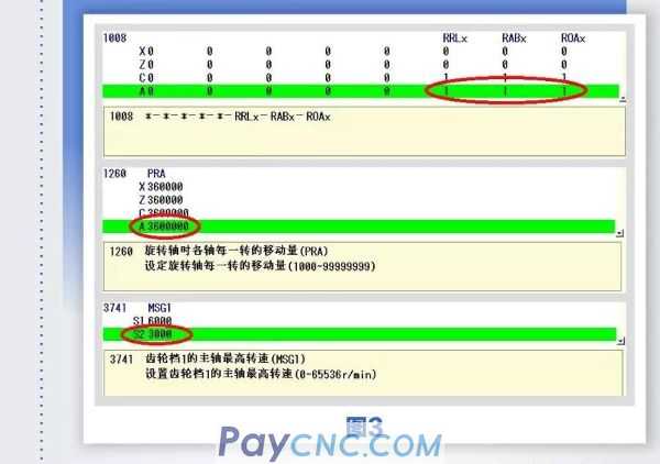
Power on the system again. Then modify the parameters according to the following figure:
【System parameters】
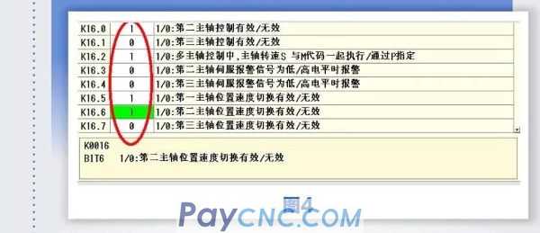
Ladder diagram PLC data
[System]-[Ladder Diagram]-[PLC Data]-[K Setting]
Set servo parameters
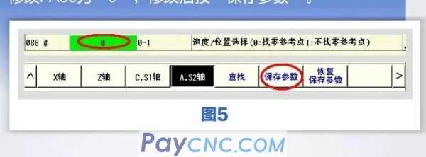
[System]-[GSKLink]-[Servo]-[Servo parameters]-[A, S2 axis]. Spindle switching and AS axis contour control need to find the zero reference point to modify PA88 to "0", and press "Save parameters" after modification.
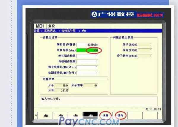
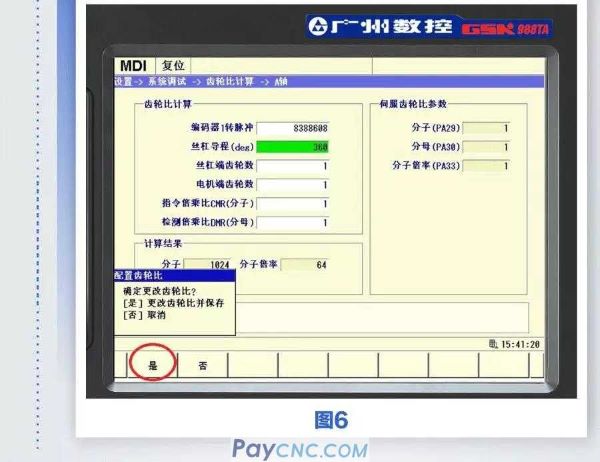
02Set the electronic wheel ratio of C axis
[Settings]-[System debugging], enter "gear ratio calculation". Set the screw lead to "360" and press "Calculate" to save the calculated result and guide the servo.
03The first power head speed/position switching control
In MDI mode, press the program key and execute M63S300 in the "MDI program" interface, the power head can rotate, indicating that the speed mode debugging is normal. Then execute the M16 command, if the system does not generate an alarm, it means that it has successfully switched to the position control mode. After executing G50 A0, execute A3600 again to observe whether the power head has rotated ten times to stop the starting point just now, and verify whether the gear ratio setting is correct.
|
 |
| Products Catalogue | Home | About Us | Retrofit | Download | News | Tech Support | Contact Us | |
|
|
|