Today, I will discuss with you the method of writing specific application programs. We will take the programming method of the control system of the material handling trolley as an example to explain.
Material trucks are mainly used to transport processed workpieces, and are relatively common transportation equipment in the production workshops of industrial and mining enterprises. The material carrier is driven by a three-phase AC asynchronous motor. The change of its movement direction is mainly realized by the forward and reverse rotation of the motor. When the control system is operating normally, it is generally set to continuous operation (automatic control). But in the process of debugging the system or equipment maintenance, it is often necessary to set the system to jog control (manual control), so the control of the material carrier is actually the motor jog, continuous forward and reverse control.
The material carrier is driven by a three-phase AC asynchronous motor and can run left and right, as shown in Figure 1. The specific control requirements are as follows:
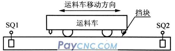
1. In jog control, press the jog forward button, the motor will run forward and jog, and the material will move left in the year; press the jog reverse button, the motor will run in reverse jog, and the material carrier will move right.
2. In continuous control, press the forward button, the motor will continue to rotate forward, and the transport vehicle will continue to move left; press the reverse button, the motor will continue to reverse, and the transport vehicle will continue to move right; press the stop button, the transport vehicle will stop at any time.
3. The material carrier should have software and hardware interlocking control functions
It is required to try to write PLC control programming (ladder diagram) with the programming components and methods that have been learned before:
(1) Programming with contact coil instructions;
(2) Programming with set reset instruction;
(3) Program with jump and jump label instructions.
1. Design electrical schematic diagram
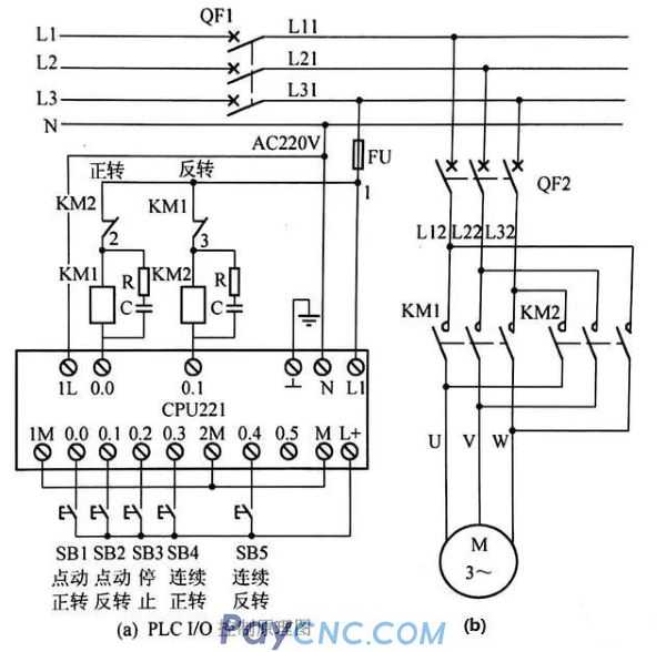
1. Choose electrical components and PLC models
Input signal: 1 jog forward button, 1 jog reverse button, 1 continuous forward button, 1 continuous reverse button, 1 stop button, 5 input signals in total, 5 inputs are required Terminal, so PLC input requires at least 5 points. (It is explained here that the limit is not considered due to space reasons).
Output signal: 1 forward contactor, 1 reverse contactor, occupying two PLC output terminals, so PLC output requires at least 2 points. Checking the Siemens PLC user manual shows that the CPU221 host has 6 inputs and 4 outputs, which can meet the actual requirements of 5 inputs and 2 outputs. Because PLC controls the motor, the relay output type PLC can meet the requirements, just choose the CPU221 relay output type PLC.
2. Design electrical schematic diagram
The electrical schematic diagram is shown in Figure 2.
2. Control program design
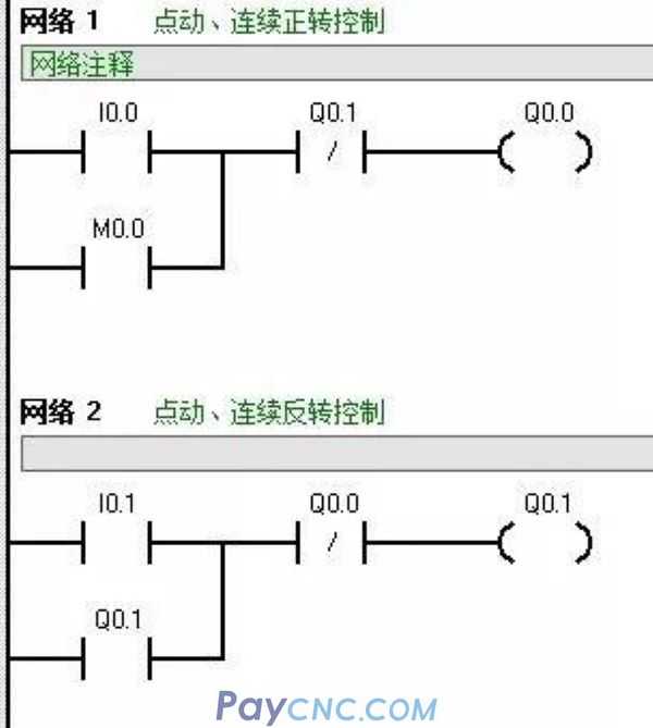
1. Programming with contact instructions
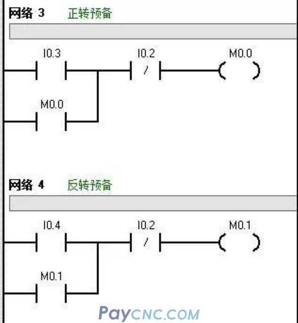
The control requirements of the material carrier are both a bit moving and continuous forward and reverse control functions. After the intermediate relay is used for state conversion, it is easy to achieve the requirements. As shown in Figure 3, network 1 and network 3 realize both jog and It can continuously control forward rotation, and network 2 and network 4 realize both jog and continuous reverse rotation control.
2. Programming with set reset instruction
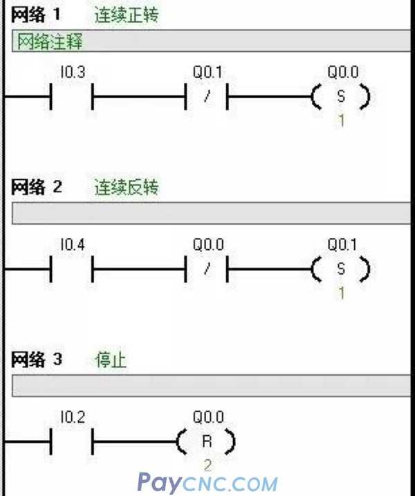
Programming with the set position reset instruction can also realize the continuous control of the motor, and its running program is shown in Figure 4 (1).
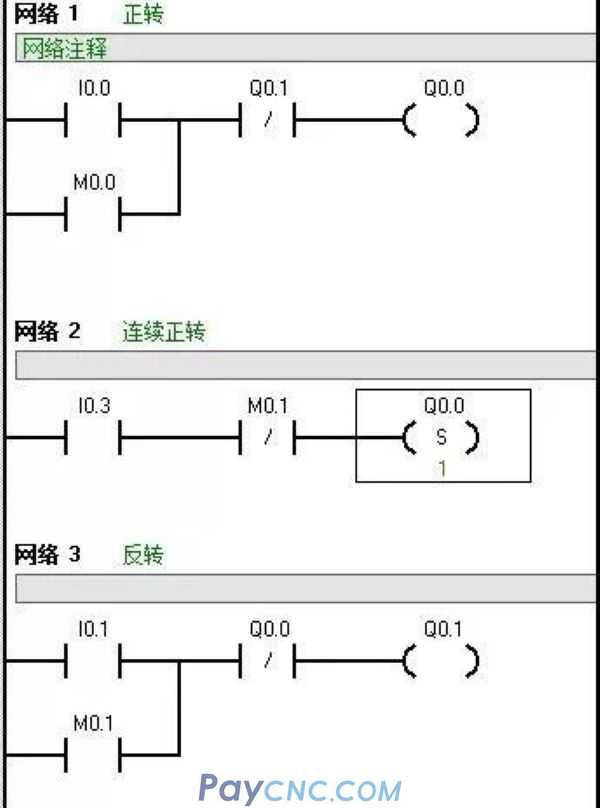
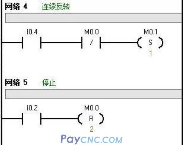
Jog control cannot use the set reset instruction, but can only be programmed with the contact coil instruction. The operating program of the motor with both jog and continuous control functions is shown in Figure 4 (2).
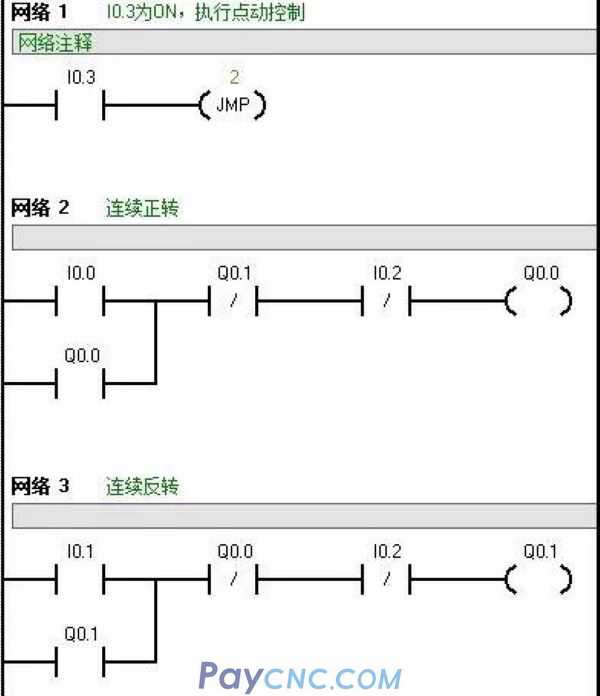
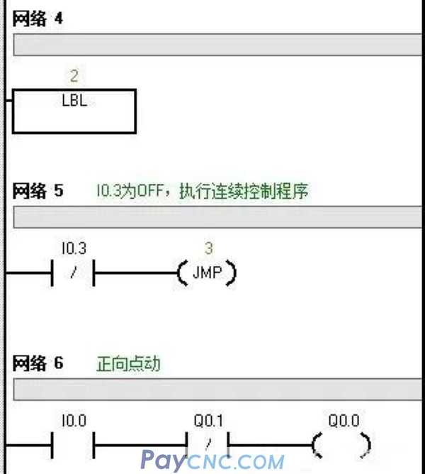
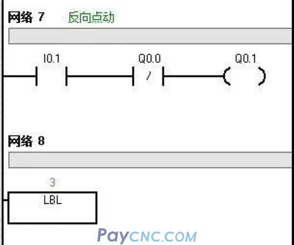
3. Programming with jump and jump label instructions
In the front, 5 buttons are used to realize the jog and continuous start and stop control of the material carrier. In fact, the jog and continuous control modes can also be selected by the rotary switch. At this time, the forward and reverse stop buttons are still needed, and the electrical schematic diagram has slightly changed. Input signal: 1 rotary switch, 1 forward rotation start button, 1 reverse rotation start button, 1 stop button, at least 4 points are required for input. The output signal is the same as before, one for each contactor coil, at least 2 points are required. Still choose CPU221 (input 6 points, output 4 points) relay output type.
The electrical schematic diagram can be slightly modified on the basis of Figure 1. The input signal uses fewer buttons, and the electrical schematic diagram will not be redrawn here. In the program I0.3 assumes that the connection is inching and the disconnection is continuous, and the control program As shown in Figure 5.
Any actual control program can be written in different ways. What kind of program is appropriate depends on whether the program is simple to write, easy to maintain, and whether it is reliable to run and minimize redundancy.
|
 |
| Products Catalogue | Home | About Us | Retrofit | Download | News | Tech Support | Contact Us | |
|
|
|