1. Understand the classification, composition and characteristics of various valves;
2. Master the function and working principle;
3. Master the function of reversing valve position through slide valve;
4. Master the working principle, performance and difference of pressure and flow valves.
The hydraulic valve is to control and adjust the liquid pressure, flow direction, and flow rate required by the hydraulic system to meet the requirements of the actuator to overcome the external load and change the direction of movement and the speed of movement.
7.1 Overview
Classification of hydraulic valves
Classified by structure
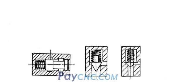
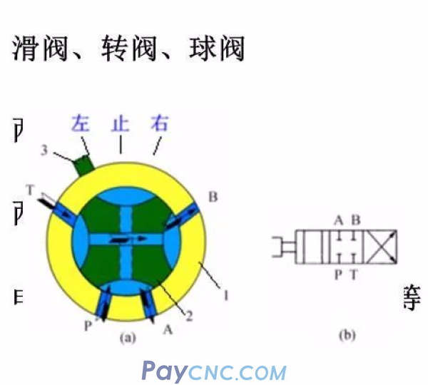
The "spool valve" slide is a gap seal, and there is a certain seal between the valve core and the valve port.
Length, so there is a dead zone in the movement of the spool valve.
Poppet valve The half cone angle of the poppet valve core is generally 12°~20°, when the valve port is closed
Line sealing, good sealing performance and sensitive action
The performance of the ball valve is the same as that of the poppet valve
Classified by function
Pressure control valve Valves used to control and adjust the hydraulic pressure of the hydraulic system, such as relief valves, pressure reducing valves, sequence valves, etc.
Flow control valve Valves used to control and adjust the flow of hydraulic system fluid, such as throttle valve, speed control valve, proportional flow valve, etc.
Directional control valve Valves used to control and change the direction of fluid flow in the hydraulic system, such as one-way valves, hydraulic control one-way valves, reversing valves, etc.
Classified by control method
Fixed value or on-off control valve Valves whose controlled quantity is fixed value, including ordinary control valves, cartridge valves, and superimposed valves.
Proportional control valve Valves whose controlled quantity changes continuously in proportion to the input signal, including ordinary proportional valves and electro-hydraulic proportional valves with internal feedback
Servo control valve A valve whose controlled quantity changes continuously in proportion to the deviation signal (between output and input), including mechanical-hydraulic servo valves and electro-hydraulic servo valves.
Digital control valve A valve that uses digital information to directly control the opening and closing of the valve port to control the pressure, flow, and direction of the liquid flow. It can be directly interfaced with a computer without a D/A converter.
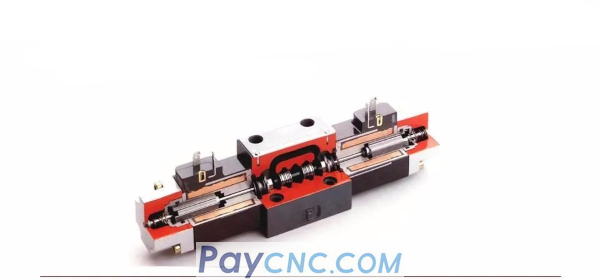
Basic structure of hydraulic valve
It includes a valve core, a valve body and a device that drives the valve core to move relative to the valve body.
The driving device can be a manual adjustment mechanism, a spring or an electromagnet, and sometimes hydraulic pressure is applied.
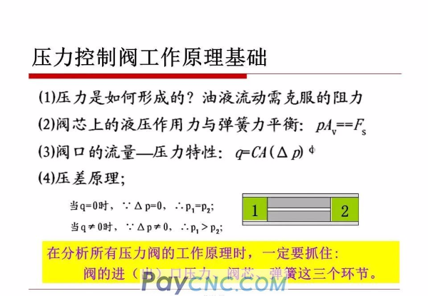
Basic working principle
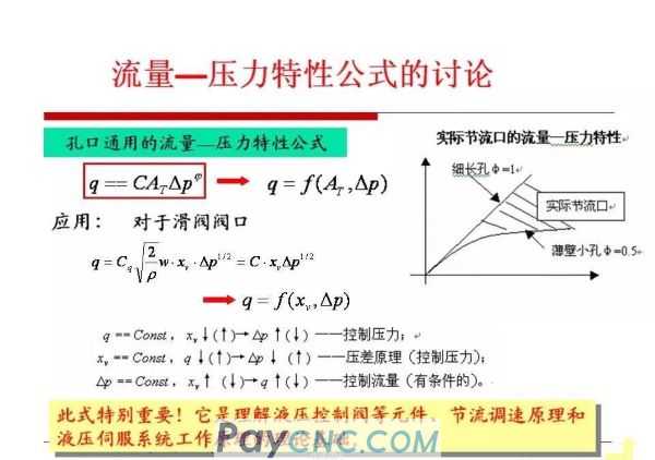
The relative movement of the valve core in the valve body is used to control the opening and closing of the valve port and the size of the valve port to realize the control of pressure, flow and direction.
The flow q flowing through the valve port is related to the pressure difference p before and after the valve port and the valve port area A, which always meets the pressure flow equation; whether the force acting on the valve core is balanced requires specific analysis.
Basic requirements for hydraulic valves
1. The action is sensitive, reliable in use, and the shock and vibration should be small during work.
2. When the valve port is fully open, the fluid pressure loss is small; when the valve port is closed, the sealing performance is better.
3. The controlled parameter (pressure or flow) should be stable, and the amount of change should be small when disturbed by the outside world. (It is very important for relief valve and throttle valve)
4. Compact structure, convenient installation, adjustment, maintenance and maintenance, and good versatility.
7.2 Directional control valve
Function: Used to control the direction of oil flow or the flow of liquid is interrupted.
Each oil port has only two states: non-make or break
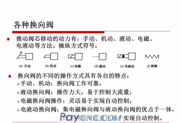
Classification: One-way valve (divided into: ordinary one-way valve and hydraulic control one-way valve according to the control method) Reversing valve (according to the way of operating the spool movement can be divided into: manual, motorized, electromagnetic, hydraulic, electro-hydraulic Move etc.)
1. Check valve
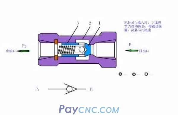
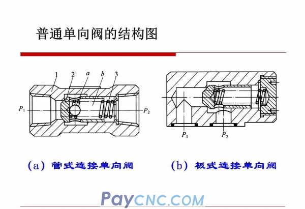
Ordinary check valve
Oil enters at the right end, pressure oil acts on the right end of the valve core, overcomes the spring force at the left end to make the valve core move to the left, the valve core opens, and the oil flows out from the left end;
If the oil enters the left end, the pressure oil acts in the same direction as the spring, so that the valve core is pressed tightly on the valve seat hole, the valve port is closed, and the oil is blocked and cannot pass.
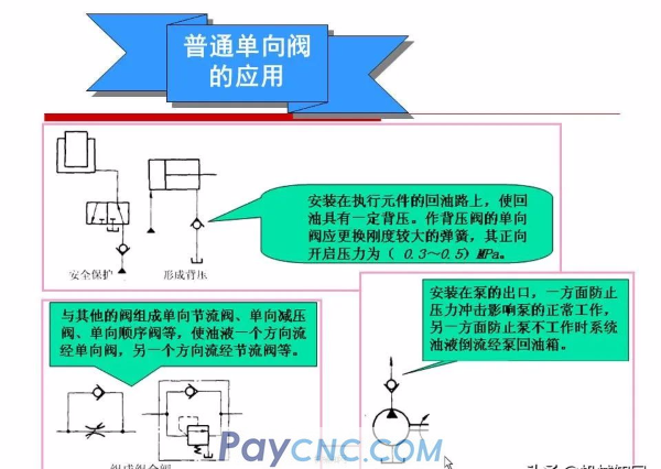
It is required that the pressure loss of the one-way valve is small when the forward flow passes, and the sealing performance is good when the reverse shutoff. The spring acting on the valve core only has a reset function, and its opening pressure is only (0.03~0.05) MPa. When the reverse cut-off occurs, it is sealed by the cone or ball valve core and the sealing line on the valve body, and the sealing force increases with the pressure. However, it increases and the sealing performance is good.
Application of ordinary check valve
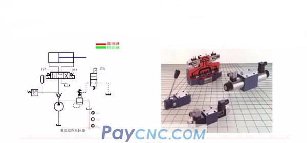
Isolation function: Double pumps supply oil, and the one-way valve is used to separate the oil circuit to prevent high and low pressure interference.
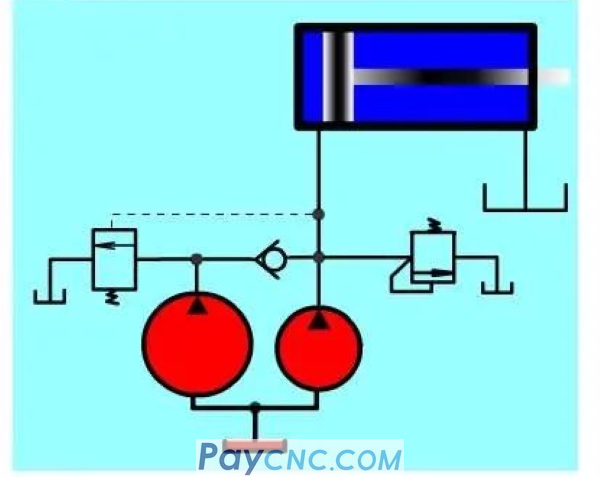
When fast forwarding: The system pressure is low, and the oil is supplied by double pumps.
When working: the load increases, the system pressure rises, the hydraulic control sequence valve opens to unload the low-pressure large-flow pump (left), and the one-way valve closes at this time, and the high-pressure small-flow pump (right) supplies oil to the system alone , Realize slow motion.
2. Hydraulic control check valve

When pressure oil is not passed through the control port, the oil can only flow from P1-P2;
When pressure oil is passed through the control port, both forward and reverse oil can pass freely.
Application of hydraulic control check valve
The hydraulic control check valve is widely used in hydraulic systems, mainly using the good sealing performance of the hydraulic control check valve poppet valve.
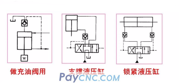
It is generally believed that the spool valve is a gap seal, and leakage is inevitable, and the poppet valve is a line seal and cannot be leaked.
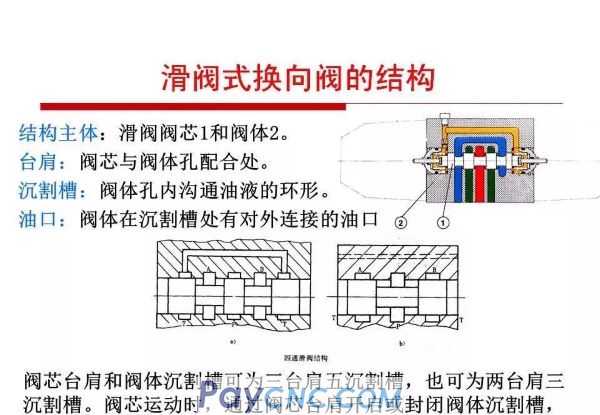
Reversing valve
Use the spool to move relative to the valve body hole to make the oil circuit on, off, or change the direction of the oil flow, so that the hydraulic actuator can start, stop or change the direction of movement.
Classification of reversing valve
According to the structure
Number of main oil passages connected by valve body
According to the working position of the spool in the valve body
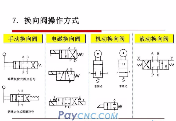
According to the way of operating the spool movement
 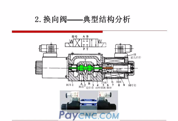 
Reversing valve-reversing principle
Spool valve naming
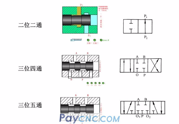
The main oil port distributed on the valve body is called "pass", excluding the control oil port and the leakage oil port. The different stable working positions of the spool valve core relative to the valve body are called "positions"
The spool valve type reversing valve with X spindle ports and Y stable working positions is called Y-position X-way reversing valve.
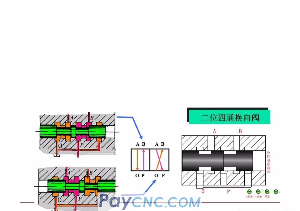
2. The meaning of the graphic symbols of the reversing valve
1) Use a box to indicate the working position of the valve. There are a few boxes to indicate a few "positions".
2) There are several main oil ports connected to the outside on a box, which means how many "pass". 3) Use the arrow in the box to indicate that the oil circuit is connected at this position, but the arrow direction is not
Must indicate the actual flow direction of the liquid flow.
4) The symbol "一" or "〦" in the box indicates that this passage is closed by the valve core, that is, it is blocked. 5) Usually the oil port connecting the directional valve and the system oil supply line is indicated by P, and the oil port connected to the oil return line
The oil return port is indicated by o, and the working oil port connected with the actuator is indicated by the letters A and B.
6) The reversing valve has two or more working positions, one of which is the normal position, that is, the position where the spool is not under the control force. The middle position in the graphic symbol is the normal position of the three-position valve. The two-position valve using spring return takes the passage state in the box close to the spring as its normal position. When drawing a hydraulic system diagram, the oil circuit should generally be connected to the normal position of the reversing valve.
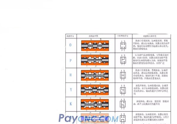
2. The central function of the reversing valve-spool valve
When the spool of the three-position reversing valve is in the middle position, there are different communication modes between the ports, which can meet different usage requirements. This connection mode is called the neutral function of the reversing valve.
Spool valves with different spool valve functions have a universal valve body, only the size and shape of the spool shoulder are different. Application of spool valve neutral function: to meet the working requirements of the system when the actuator is not working;
H, K, M can unload the pump, O, M can stop the hydraulic cylinder at any position, H, Y can float the hydraulic actuator, and P can realize the differential connection of the hydraulic cylinder.
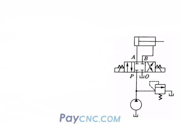
Neutral function application
System pressure retention: the middle position "o" type, as shown in the figure, when the P port is blocked, the oil needs to flow back to the tank from the overflow valve at this time, increasing power consumption; but the hydraulic pump can be used in a multi-cylinder system.
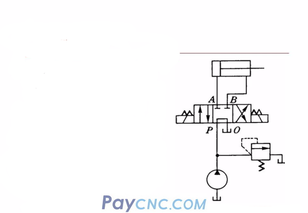
Neutral function application
System unloading: middle position "M" type, as shown in the figure, when the direction valve is in the middle position, because the P and O ports are connected, the oil output from the pump can flow back to the tank without passing through the overflow valve. tank. Therefore, the output pressure of the pump is approximately zero, which is also called pump unloading to reduce power loss.
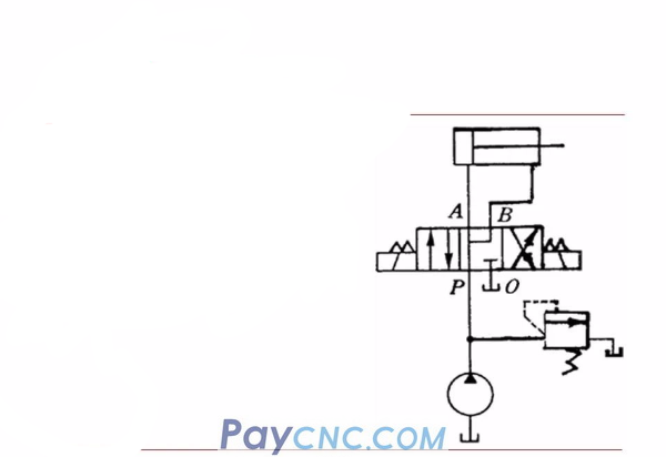
Neutral function application
Hydraulic cylinder fast forward: Neutral "P" type, as shown in the figure, when the reversing valve is in the neutral position, because P, A, B are connected, it can be used as a differential circuit.
  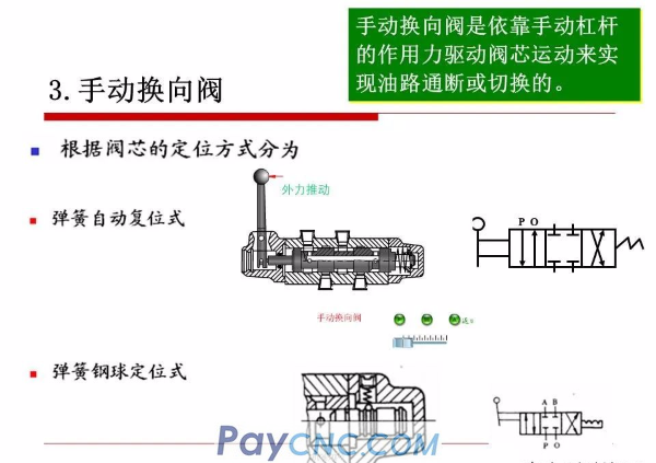
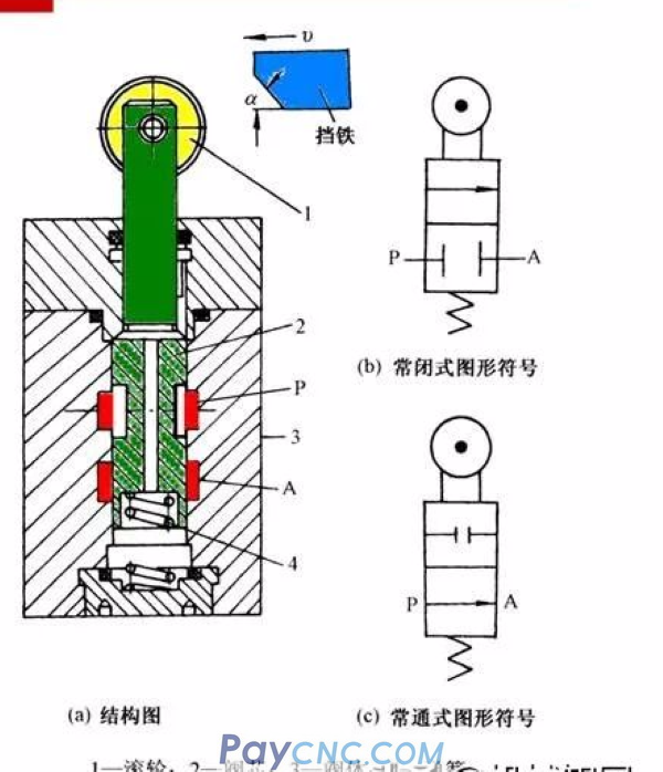
4. Motorized reversing valve
Also known as: stroke reversing valve, which relies on the stroke stop (or cam) installed on the actuator to push the spool to achieve reversal
When the stopper presses down the roller 1 and moves the valve core 2 to the lower end position, the oil ports P and A gradually communicate; when the stopper removes the roller, the valve core is reset by the bottom spring 4, and the oil ports P and A gradually shut down.
Changing the oblique angle of the stop iron slope or the shape of the cam profile can change the speed of the valve movement, so the time of the reversing process can be adjusted, so the reversing performance is better.
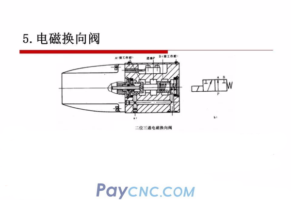
5. Electromagnetic reversing valve
The movement of the spool is based on the combined action of electromagnetic force and spring force. The electromagnet must not be electrified. The spool is in the left extreme position (right position) under the action of the spring at the right end, and the oil port P is connected to A, but B is not connected; the electromagnet is energized to generate an electromagnetic attraction force, which pushes the spool to move to the right through the push rod , The valve works in the left position, port P and B are connected, and port A is blocked.
The electromagnet can be DC or AC.
If the electromagnets at both ends and the spring centering mechanism are combined, a three-position electromagnetic reversing valve can be formed. The electromagnets are energized for the left and right positions, and not for the neutral position.
Both ends cannot be powered at the same time
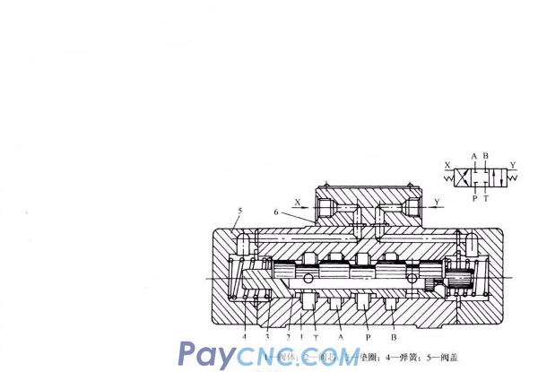
6. Hydraulic reversing valve
The hydraulic reversing valve uses pressure oil to push the spool to shift to realize the on-off or switching of the oil circuit.
When the two control oil ports X and Y do not pass pressure oil, the valve core 2 is in the neutral position under the action of the springs 4 at both ends. When the control pressure oil flows into the oil cavity at the left end of the spool from X, the spool is pushed to the right end, and the oil ports P and B are connected, and A and T are connected;
When the control pressure oil flows into the oil chamber at the right end of the spool from Y, the spool is pushed to the left, and the oil ports P and A are connected, and B and T are connected, realizing the liquid flow reverse.
The thrust of the hydraulic control spool is suitable for occasions with high pressure, large flow and long valve stroke.
  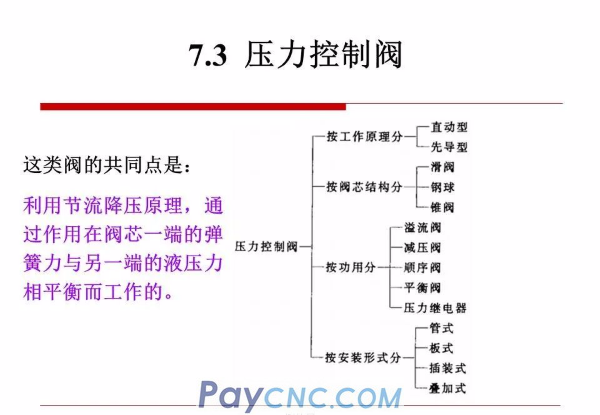 
Relief valve
The overflow valve is used to set the working pressure of the system or limit the maximum working pressure through the overflow of the valve port to prevent the system from overloading.
It is needed in almost all hydraulic systems, and its performance has a great influence on the normal operation of the entire hydraulic system.
According to its structural form and basic action mode, it is divided into:
Direct-acting relief valve
Pilot operated relief valve
Direct-acting relief valve
The direct-acting relief valve relies on the pressure oil in the system to directly act on the spool, and is balanced with the spring force to control the opening and closing actions of the spool.
The pressure oil enters from port P and acts on the bottom of the valve core through the orifice 1. When the hydraulic pressure acting on the valve core 3 is greater than the spring force, the valve port opens, causing the oil to overflow.
Adjust 5 downwards, then the force to open the spool 3 increases? Or reduce it?
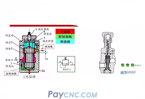
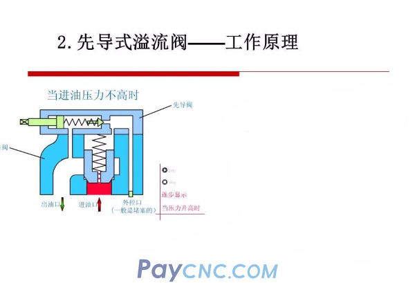
Pilot operated relief valve-structure
It consists of a pilot valve and a main valve.
The pilot valve is actually a small flow direct-acting relief valve, and its spool is a cone valve. The inlet pressure value is mainly determined by the top compression amount of the pressure regulating spring of the pilot valve.
There is a damping hole on the main valve core, and the active area of the upper cavity is slightly larger than the active area of the lower cavity, and the spring only plays a reset function when the valve port is closed.
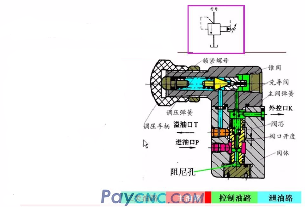
Pilot operated relief valve-working principle
The opening of the main spool is based on the pressure difference formed by the fluid flowing through the orifice. The damping hole is generally a slender hole with a small diameter of 0.8~1.2mm, and the hole length is 1=8~12mm, so it is easy to be blocked during operation. Once blocked, the main valve port is normally open and cannot be adjusted.
■ There is a control port in the front chamber of the pilot valve for unloading and remote control.
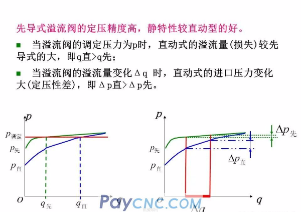
The degree to which the pressure at the inlet of the overflow valve is constant with the change of the overflow flow of the valve port is an important indicator to measure the static characteristics of the overflow valve.
In fact, the opening amount of the overflow valve changes when it is working, and the change of the opening amount causes the overflow flow to change, and it will inevitably cause the pressure to change. The higher the pressure, the greater the spring stiffness required, therefore, the greater the pressure change when the overflow flow changes.
The pilot-operated relief valve has high constant pressure accuracy, and its static characteristics are better than those of the movable type.
Compare:
When adjusting the pressure nut, the spring deformation force of the direct-acting relief valve is large, and the pressure adjustment is laborious, so the direct-acting relief valve is suitable for systems with low pressure, small flow, and low pressure stability requirements.
The pilot-operated relief valve consists of two parts: the pilot valve and the main valve. The pressure on the other end of the spool is adjusted by the pilot valve. The pressure-bearing area of the pilot valve is small and the sensitivity is high, so its spring force is not large. , The adjustment is labor-saving and flexible.
It can be seen that the pilot-operated relief valve is suitable for systems with high pressure and large flow and high pressure stability requirements.
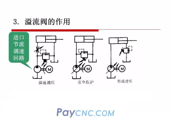
Overflow pressure regulation: keep the system pressure basically unchanged during the continuous overflow process.
Safety protection: also known as safety valve, used for overload protection.
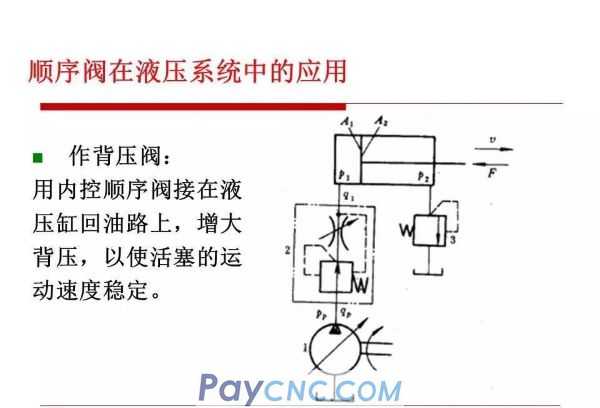
Form back pressure: connect to the oil return line to make the system stable.
4. The performance requirements of the hydraulic system for the relief valve
1. High precision of constant pressure.
2. The sensitivity should be high. For example, when the pressure is adjusted by overflow, when the hydraulic cylinder suddenly stops moving, the overflow valve should be opened quickly. Otherwise, the oil output by the quantitative pump will suddenly rise due to the failure to discharge in time, and exceed the set pressure of the overflow valve, which will increase the forces on the components and auxiliary systems in the system and affect its life.
3. The work should be stable and free of vibration and noise.
4. When the valve is closed, the seal should be good and the leakage should be small.
For the overflow valve that is frequently opened, the first three performances are mainly required; for the safety valve, the second and fourth two performances are mainly required. In fact, both the relief valve and the safety valve are valves with a unified structure, but they have different functions under different requirements.
Pressure reducing valve
The pressure reducing valve is a pressure control valve that uses liquid flow to flow through the gap to produce pressure loss, so that the outlet pressure is lower than the inlet pressure
According to different adjustment requirements, there are:
The outlet pressure is a fixed value-fixed value reducing valve;
The pressure difference between inlet and outlet remains unchanged-fixed differential pressure reducing valve;
The inlet and outlet pressure is proportional-constant proportional pressure valve.
Among them, the fixed value pressure reducing valve is the most widely used, also referred to as the pressure reducing valve
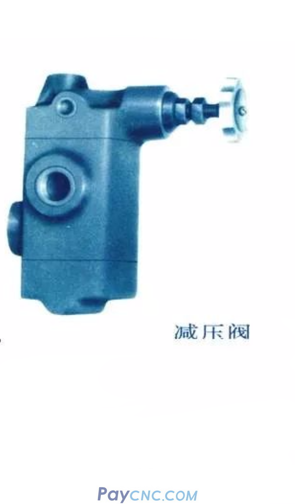
The pressure reducing valve consists of a pilot valve and a main valve
The inlet pressure oil flows to the outlet through the main valve port, and the outlet pressure oil is led to the lower cavity of the main spool, and then into the upper cavity of the main spool and the front cavity of the pilot valve. When the outlet pressure is greater than the set pressure of the pressure reducing valve, the pilot The valve port is opened, the main valve core moves up, the gap of the main valve port is closed, the pressure reducing valve plays a role in reducing pressure and ensuring the outlet pressure
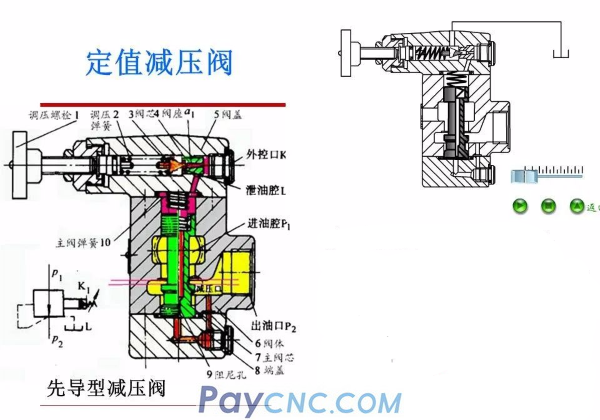
Features and functions of pressure reducing valve
Features: Decompression is the outlet pressure control, ensuring that the outlet pressure is a constant value
The valve port of the pressure reducing valve is normally open, and the inlet and outlet ports are connected;
The pressure reducing valve has a separate drain port
The outlet pressure of the pressure reducing valve goes to work again, and the pressure is not zero.
The pressure reducing valve has the same remote control port as the overflow valve.
Function: The role of the pressure reducing valve: pressure reducing and stabilizing. Decompression is to bring higher into
The outlet pressure p1 is reduced to a lower outlet pressure p2; to stabilize the outlet pressure is to stabilize the outlet pressure at the set value.
Using one oil source can provide two or several different pressure outputs at the same time. It is widely used in the clamping, lubrication and control systems of various hydraulic equipment. In addition, when the oil pressure is unstable, a pressure reducing valve can be connected in series to obtain a stable lower pressure.
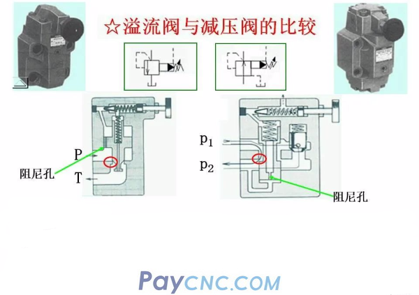
Comparison of relief valve and pressure reducing valve
the difference:
1. The overflow valve keeps the pressure at the inlet basically unchanged, while the pressure reducing valve keeps the outlet pressure basically unchanged.
2. When not working, the oil inlet and outlet ports of the relief valve are blocked, while the inlet and outlet ports of the pressure reducing valve are communicated.
3. In order to ensure a constant setting value of the outlet pressure of the pressure reducing valve, its pilot valve spring cavity needs to be separately connected to the oil tank through the drain port.
; And the oil outlet of the overflow valve is connected to the oil tank, so the spring cavity of the pilot valve and the leaking oil can communicate with the oil outlet through the passage on the valve body, and there is no need to connect the oil tank separately.
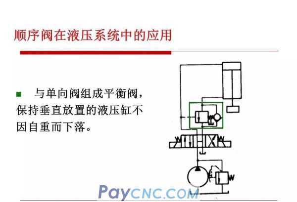
Sequence valve
Sequence valve is a kind of pressure valve that uses pressure to control the opening and closing of valve ports. It is named after the sequence of actions used to control multiple actuators.
Depending on the control pressure, the sequence valve can be divided into
Internal control type: use the inlet pressure of the valve to control the opening and closing of the spool
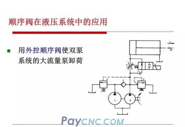
External control type: use external control pressure oil to control the opening and closing of the spool (ie hydraulic control sequence valve)
Depending on the structure, the sequence valve can be divided into
Direct-acting: generally used in low-voltage systems
Pilot type: used in medium and high voltage systems
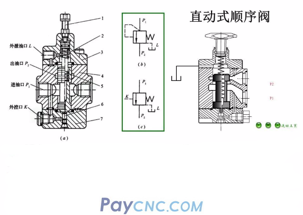
After the pressure oil passes through the P1 port into the oil chamber, it passes through the holes in the valve body 4 and the bottom cover 7 and enters the bottom of the control piston 6.
When the inlet pressure P1 is lower than the preset pressure of the pressure regulating spring 2, the valve core does not move and the valve port is closed.
When the inlet pressure increases and is greater than the preload of spring 2, the valve core rises, the valve port opens, and the inlet and outlet ports P1 and P2 are connected
The main difference between sequence valve and relief valve
1) The oil outlet of the sequence valve is connected to the load oil circuit, and the outlet oil circuit of the overflow valve is directly connected to the oil tank;
2) The drain port of the sequence valve is separately connected to the tank, and the drain of the overflow valve flows back to the tank through the internal port of the valve body and the outlet of the valve;
3) The inlet pressure of the sequence valve is determined by the working conditions of the hydraulic system. When the inlet pressure is lower than the setting pressure of the spring, the valve port is closed; when the inlet pressure exceeds the setting pressure of the spring, the valve port is opened and the oil circuit is connected. , The outlet pressure oil does work on the downstream load.
The maximum pressure at the inlet of the overflow valve is limited by the pressure regulating spring, and because the liquid overflows back to the tank, all the energy of the liquid is lost.
    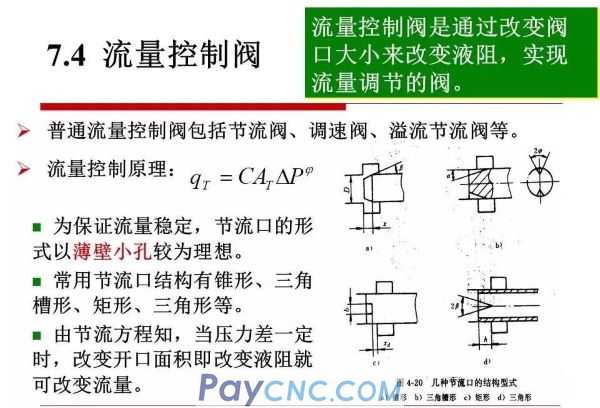
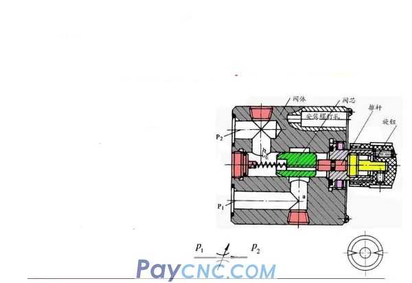
Ordinary throttle valve
The throttle valve is essentially equivalent to a variable orifice. With the help of a control mechanism, the valve core moves relative to the valve body hole to change the flow area of the valve port.
Structural principle: The main parts are valve core, valve body and push rod. The lower side of the valve body is the oil inlet, and the upper side is the oil outlet.
One end of the valve core is provided with a triangular tip groove, and the other end is machined with threads. Rotating the valve core can move axially to change the flow area of the valve port. In order to balance the hydraulic radial force, the triangular grooves must be arranged symmetrically
Throttle clogged and minimum stable flow
The main reason: When the flow valve is working, the flow cross section of the orifice is usually very small, especially when the system speed is low. Therefore, the orifice is easily blocked by mechanical impurities such as metal chips, dust, sand, sludge, etc. contained in the oil, and colloidal deposits, oxides and other impurities generated by the oxidation of the oil under high temperature and high pressure.
Performance When the orifice is blocked, the oil flow stops, and the pressure increases quickly until the blocked hole is flushed, so the flow suddenly increases. This process is repeated continuously, causing periodic flow pulsation. The smaller the opening, the more serious the pulsation phenomenon, even when the valve port is not completely closed, the flow will be cut off.
Throttle clogged and minimum stable flow
Measures to reduce clogging
Choose a thin blade orifice with a large hydraulic radius;
Precise filtration and regular replacement of hydraulic oil;
Reasonably choose the pressure difference before and after the orifice;
Use oil with good anti-oxidation stability, reduce the surface roughness of the orifice, etc.
Minimum stable flow
Minimum flow rate without throttling and clogging
The smaller the minimum stable flow, the better the flowability of the orifice of the throttle valve? ? ? The lowest stable speed that the system can obtain? ? That is, the speed range of the valve? ? In order to ensure the speed stability of the system at low speed, the minimum stable flow must be less than the flow value required for the system to run at the lowest speed
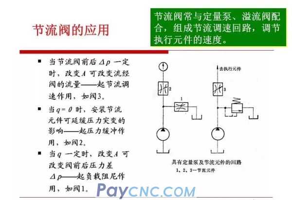
Ordinary throttle valve has poor rigidity. After the throttle opening is adjusted, the flow through it is affected by the load change, and cannot maintain the stability of the moving speed of the actuator. Therefore, it is only suitable for occasions where the work load changes little and the speed stability requirements are not high. .
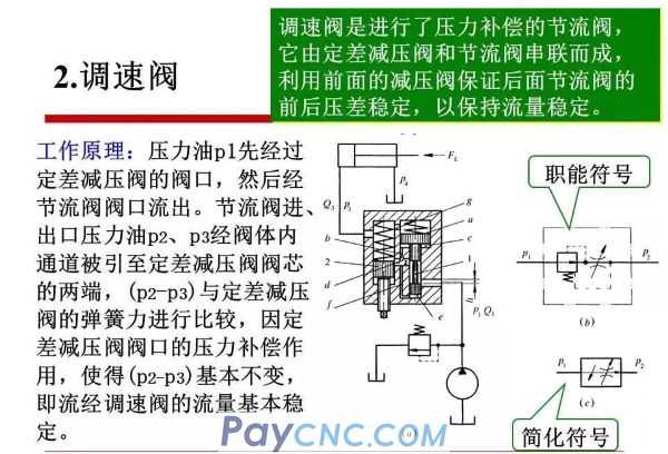
In order to improve the performance of the speed control system, the throttle valve is usually compensated, that is, measures are taken to keep the pressure difference before and after the throttle valve constant when the load changes.
There are two ways to keep the pressure difference between front and rear basically unchanged:
A: The fixed differential pressure reducing valve and the throttle valve are connected in series to form a speed regulating valve;
B: Connect the regulator relief valve and the throttle valve in parallel to form an overflow throttle valve.
These two kinds of valves use the change of flow to cause the change of oil pressure, and use the negative feedback action of the spool to automatically adjust the pressure difference of the throttling part to keep it unchanged.
     |
 |
| Products Catalogue | Home | About Us | Retrofit | Download | News | Tech Support | Contact Us | |
|
|
|