1. The concept of tolerance and fit
(1) Interchangeability of parts
When the machine is assembled in batch production, a batch of matching parts are required to be processed according to the requirements of the part drawing. Without any selection or repair, any pair can be assembled to meet the design work performance requirements. This property is called interchangeability. The parts are interchangeable, which can bring convenience to the assembly and repair of the machine, and also provide the possibility for the modern mass production of the machine.
(2) Terms related to tolerance
During the processing of the parts, it is impossible to process the dimensions of the parts absolutely accurately due to the influence of the accuracy of the football machine tool, tool wear, and measurement errors. In order to ensure interchangeability, the machining error of the part size must be limited within a certain range, as an example, explain the relevant terms of tolerance (shaft, similar).
1. Basic size
According to the strength and structural requirements of the parts, the size is determined during design. The value should prefer standard diameter or standard length.
2. Actual size
The size obtained by measurement.
3. Limit size
Two limit values for allowable size changes. It is determined based on the basic size. The larger of the two limit values is called the maximum limit size; the smaller one is called the minimum limit size.
4. Size deviation (abbreviated as deviation)
The algebraic difference of a certain size minus its basic size. The size deviations are:
Upper deviation = maximum limit size-basic size
Lower deviation = minimum limit size-basic size
The upper and lower deviations are collectively called limit deviations, and the upper and lower deviations can be positive, negative or zero.
The national standard stipulates: the upper deviation code of the hole is ES, the lower deviation code of the hole is EI; the upper deviation code of the shaft is es, and the lower deviation code of the shaft is ei.
5. Dimensional tolerance (referred to as tolerance)
Allowable size variation.
Dimension tolerance = maximum limit size-minimum limit size = upper deviation-lower deviation
Because the maximum limit size is always greater than the minimum limit size, that is, the upper deviation is always greater than the lower deviation, the dimensional tolerance must be a positive value.
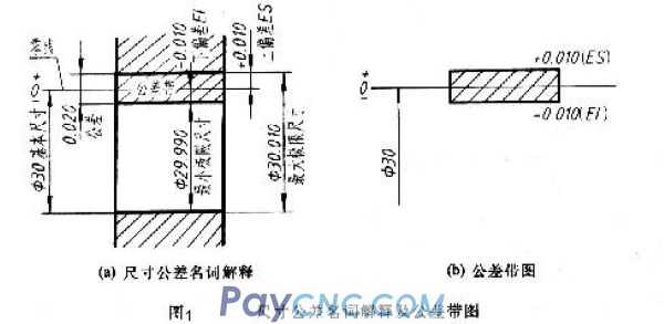
The aperture shown in Figure 1a:
Basic size = Ø30
Maximum limit size = Ø30.010
Minimum limit size = Ø29.990
Upper deviation ES = maximum limit size-basic size
=30.010-30=+0.010
Lower deviation EI = minimum limit size-basic size
=29.990-30=-0.010
Tolerance = maximum limit size-minimum limit size
=3.010-29.990=0.020
=ES-EI=+0.010-(-0.010)=0.020
If the actual size is between Ø30.010 and Ø29.990, it is qualified.
6. Zero line, PR zone and tolerance zone diagram
As shown in Figure 1b, the zero line is a baseline used to determine the deviation in the tolerance zone diagram, that is, the zero deviation line. Usually the zero line represents the basic size. Mark "0", "+" and "—" at the left end of the zero line, the deviation above the zero line is positive; the deviation below the zero line is negative. The tolerance zone is an area defined by two straight lines representing the upper and lower deviations. The width and position of the tolerance zone are the two elements that constitute the tolerance zone. In order to simply explain the above terms and their relationships, they are generally represented by tolerance band diagrams in practice. Tolerance zone diagram is to draw a box in the form of an enlarged view, the zero line is noted, the width of the box indicates the tolerance value of the tolerance, and the left and right length of the box can be determined arbitrarily according to needs. In order to distinguish the tolerance zone of the shaft and the hole, the tolerance zone of the hole is generally indicated by a diagonal line; the tolerance of the shaft is indicated by a dot.
7. Standard tolerance and standard tolerance grade
Standard tolerance is any tolerance listed in national standards to determine the size of the tolerance zone. The standard tolerance level is the level that determines the accuracy of the size. The standard tolerance is divided into 20 grades, namely IT01, IT0, IT1, IT-18, which represent standard tolerances, and Arabic numerals represent standard tolerance grades. Among them, IT01 is the highest, the grade is lowered, and the IT18 is the lowest. For a certain basic size, the higher the standard tolerance level, the smaller the standard tolerance value, the higher the accuracy of the size. The national standard divides the basic size range within 500mm into 13 sections, and lists the standard tolerance values of the basic sizes of each section according to different standard tolerance levels, see table
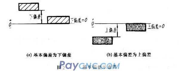
8. Basic deviation
Used to determine the upper or lower deviation of the tolerance zone relative to the position of the zero line. Generally refers to the deviation close to the zero line. As shown in Figure 2, when the tolerance zone is above the zero line, the basic deviation is the lower deviation, and when the tolerance zone is below the zero line, the basic deviation is the upper deviation.
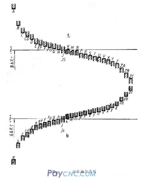
According to actual needs, the national standard specifies 28 different basic deviations for holes and shafts, as shown in Figure 3. The basic deviation values of holes and shafts can be found from the relevant tables. It can be seen from Figure 3:
(1) The basic deviation code is expressed in Latin letters, the capital letter represents the basic deviation code, and the lower case letter represents the basic deviation code of the shaft. Since the basic deviation in the figure only shows the size of the tolerance zone, one end of the tolerance zone is drawn as an opening.
(2) The deviation from A-H is the lower deviation, J-ZC is the upper deviation, and the upper and lower deviations of JS are +IT/2 and ---IT/2 respectively.
(3) The basic deviation of the axis is from a to h as the upper deviation, j to zc as the lower deviation, and the upper and lower deviations of js are +IT/2T and -IT/2 respectively. Another deviation of the hole and the shaft can be calculated from the basic deviation and standard tolerance.
9. The shaft tolerance code is composed of the standard tolerance grade code, and should be written in the same size.
For example: Ø60H8 means the tolerance zone of the hole whose basic size is Ø60, the basic deviation is H, and the standard tolerance level is 8. Another example: Ø60f7, which means that the basic size is Ø60, the basic deviation is f, and the standard tolerance level is 7-level shaft tolerance zone.
(3) Related terms for cooperation
In machine assembling, the relationship between the holes and the tolerance zone of the shaft that have the same basic size and are combined is called fit. Since the actual size of the hole and the shaft are different, "clearance" or "interference" can be generated after assembly. In the fit between the hole and the shaft, when the algebraic difference of the hole size minus the shaft size is a positive value, it is a clearance, and when a negative value is an interference.
1. Types of cooperation
The fit is divided into three categories according to the gap or interference that occurs:
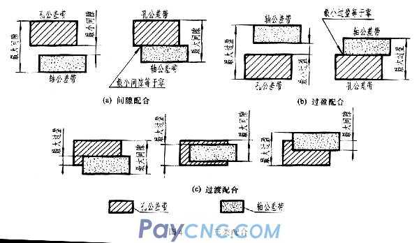
(1) The tolerance zone of the clearance fit hole is above the public relations zone of the shaft. Any pair of holes and the shaft match will become a fit with a clearance (including the minimum clearance of zero), as shown in Figure 4a.
(2) The tolerance zone of the interference fit hole is below the tolerance zone of the shaft. Any pair of holes and the shaft match are considered to have an interference fit (including a minimum clearance of zero), as shown in Figure 4b.
(3) The tolerance zone of the over-fitting hole overlaps the tolerance zone of the shaft. Choose any pair of holes to match the shaft. It may have clearance or interference fit, as shown in Figure 4c.
2. Cooperative benchmark system
National standards stipulate two benchmark systems, as shown in Figure 4.
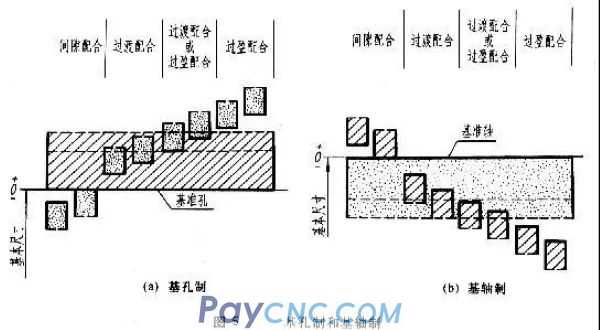
(1) The basic deviation of the basic hole system is a system in which the tolerance zone of a certain hole and the tolerance zone of the shaft of the basic deviation constitute a kind of coordination, as shown in Figure 5a. That is, the position of the tolerance zone of the hole is fixed in the fit of the same basic size, and different fits are obtained by changing the position of the tolerance zone of the shaft.
The hole made by the base hole is called the datum hole. The lower deviation of the datum hole is specified in the national standard as zero, and "H" is the basic deviation code of the datum hole.
(2) Basic shaft system The basic deviation is a system that the tolerance zone of a certain shaft and the tolerance zone of holes with different basic deviations constitute a variety of coordination, as shown in Figure 5b. That is to fix the position of the tolerance zone of the shaft in the fit of the same basic size, and obtain different fits by changing the position of the tolerance zone of the hole.
The hole made by the base axis is called the datum shaft sleeve. The upper deviation of the datum shaft is specified as zero in the national standard, and "h" is the basic deviation code of the datum shaft.
It can be seen from the basic deviation series (Figure 3):
In the basic hole system, the reference hole H is matched with the shaft, a~h (11 types in total) are used for clearance fit; j~n (5 types in total) are mainly used for over-fitting; (n, p, r may be over-fitting Or interference fit); p~zc (12 types in total) is mainly used for interference fit.
In the base shaft system, the reference shaft h is matched with the hole, A~H (11 types in total) is used for clearance fit; J~N (5 types in total) is mainly used for over-fitting; (N, P, R may be over-fitting Or interference fit); P~ZC (12 types in total) are mainly used for interference fit.
2. Selection of tolerance and fit
The selection of tolerance fit includes three items: reference system, fit category and tolerance level.
(1) Benchmark system
The national standard of the benchmark system stipulates that the base hole system is preferred. Generally speaking, machining holes is more difficult than machining shafts. The use of base holes can limit and reduce the number of fixed-value tools and measuring tools required for machining, so as to obtain more Good economic benefits.
The base shaft system is usually only used in situations where the structural design requirements are not suitable for the base hole system, or the base shaft system has obvious economic effects. For example, when the same shaft is matched with several holes with different tolerance zones (as shown in Figure 6) or a shaft that is made by cold drawing and no longer undergoes cutting processing, when it is matched with the hole, the base shaft system is adopted.
When the parts are matched with the standard, it should be determined according to the reference system selected for the standard parts. For example, the matching between the shaft ring and the shaft of the rolling bearing is the base hole system; and the matching between the seat ring and the body hole is the base shaft system.
(2) Choice of cooperation
The national standard stipulates the tolerance zone of preferred, common and general purpose holes and shafts. The priority and common coordination should be selected as far as possible according to the coordination characteristics and use functions. When the parts have relative rotation or movement, the clearance fit must be selected; when there are no keys, pins and other fasteners between the parts, and only the interference between the joint surfaces is used to achieve transmission, the interference fit must be selected as the part When relative movement is not required between them, the coaxiality is required to be high, and the power is not transmitted by the fit, the over fit is usually selected.
(3) Selection of quasi-public relations level
Under the conditions of ensuring the use of parts, a relatively low standard tolerance level should be selected as far as possible, that is, the number of standard tolerance levels is larger and the tolerance value is larger, so as to reduce the manufacturing cost of parts. Because it is difficult to machine holes, when the standard tolerance level is higher than IT8, in the basic size to 500mm, the standard tolerance level of the hole should be selected one level lower than that of the shaft (for example, the hole is level 8 and the shaft is level 7). Machining holes. Because the higher the tolerance level, the more difficult it is to process. When the standard tolerance grade is low, the shaft and hole can be matched with the same standard PR grade.
Usually IT01~IT14 are used for block gauges and gauges; IT5~IT12 are used for matching sizes; IT12~IT18 are used for non-matching sizes.
3. Tolerance and fit annotation method and look-up table
(1) Match the notation in the assembly drawing
The matching code is composed of the matching hole and the tolerance zone code of the shaft, expressed in fraction form, the numerator is the tolerance zone code of the hole; the denominator is the tolerance zone code of the shaft (when using the sloping fraction line, the sloping fraction line should be in line with the numerator and denominator The code name is flush).
From the above analysis, it can be seen that in the coordination code, if the molecule contains H, it is a basic pore coordination; if the distribution contains h, it is a basic axis coordination. If the distribution contains H and the distribution also contains h, it is a clearance fit with the base hole and the reference shaft, that is, the minimum clearance is zero. It is generally regarded as a base hole fit or a base shaft fit.
There are three forms to match the notation in the assembly drawing:
(1) Mark the matching code of the hole and shaft, as shown in Figure 7a. This injection method is the most widely used.
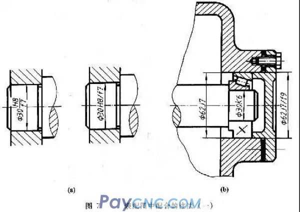
(2) When parts are matched with standard parts or purchased parts, only the tolerance zone code of the part can be marked in the assembly drawing. As shown in Figure 7b, for the fit of the journal and the rolling bearing ring, only the journal φ30K6 is injected; for the fit of the frame hole and the rolling bearing race, only the frame hole φ62J7 is injected.
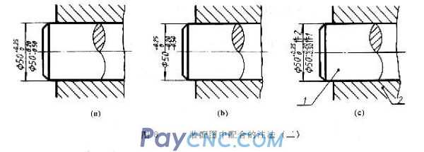
(3) Mark the limit deviation of the hole and shaft, as shown in Figure 8. This injection method is mainly used for non-standard coordination.
(2) The method of noting tolerance in the parts drawing
There are three forms of tolerance in the part drawing:
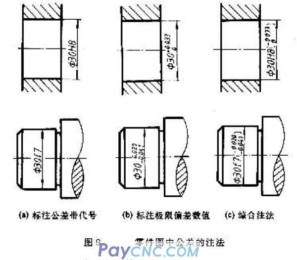
1. Mark the tolerance zone code
As shown in 9a, this injection method is commonly used in mass production in the field, because it is unified with the use of special measuring tools to inspect parts, so there is no need to inject deviation values.
2. Mark the deviation value
As shown in Figure 9b, this injection method is often used in small batch or single-piece production for comparison during processing and inspection. Pay attention to the deviation value of village injection;
(1) When the upper and lower deviation values are different, the upper deviation is noted on the upper right of the basic size, and the lower deviation is noted on the lower right and on the same bottom line as the basic size. The deviation number should be one size smaller than the basic size number, the integer digits before the decimal point should be aligned, and the decimal digits after the decimal point should be the same, as shown in the figure ф30.
(2) If the upper deviation or the lower deviation is zero, it should be abbreviated as "0", without the "+" and "-" signs in the front, and no decimal point in the back; the other deviation is written in the original position, with the ones digit "0" is aligned, as shown in ф30.
(3) If the absolute value of the upper and lower deviation coal values is the same, add "±" after the basic size, and fill in only one deviation value, the number size is the same as that of the basic size, such as ф80±0.017.
3. Simultaneously note the tolerance zone code and deviation value
As shown in Figure 9c, the deviation value should be enclosed in parentheses. This labeling form combines the advantages of the first two labeling forms, and is often used in production where products are frequently converted.
National standards stipulate that only one type of marking can be selected for tolerances on the same part drawing.
(3) Look-up table of limit deviation value
When the basic size of the hole or shaft, the basic deviation code and the standard tolerance level are determined, the upper and lower deviations of the hole or shaft can be directly checked in the limit deviation table; for the reference parts (reference hole and reference shaft) directly from the standard tolerance table Check it out.
[Example 10-3] Look up the table and write out the axis and hole deviation values of ф30 and ф18.
1. Check the axis and hole deviation value of ф30
It can be seen from the matching code that the basic size of the hole and shaft is ф30, the hole is the reference hole, and the tolerance level is 7; the basic deviation code of the matching shaft is f, the tolerance level is 6, and it is a basic hole clearance fit.
2. Check the reference hole of ф30H7. In the attached table, from the intersection of the horizontal rows of the basic size 24 to 30 and the column of H7, the upper and lower deviations are found to be μm (that is, mm), so ф30H7 can be written as ф30. 0.021 is the tolerance of the reference hole, so It can be found in the standard tolerance table that 21μm (ie 0.021mm) is found at the intersection of the horizontal row of the basic size> 18-30 and the vertical column of IT7. It can be seen that the upper deviation of the reference hole is +0.021, and the lower deviation is "0 ".
3. Check ф30f6 axis.
In the attached table 6-1, from the intersection of the horizontal row with the basic size> 24~30 and the column of f6, the upper and lower deviation is found to be μm (that is, mm), so ф30f6 can be written as ф30.
|
 |
| Products Catalogue | Home | About Us | Retrofit | Download | News | Tech Support | Contact Us | |
|
|
|