Actually demonstrate the method of tool setting once. Let everyone understand the relationship between coordinate system and tool setting more intuitively. 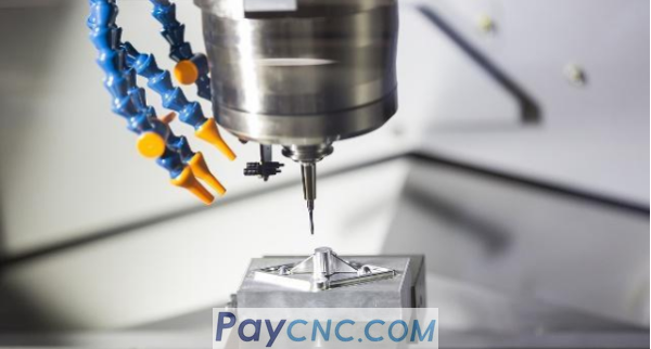
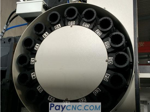
Before learning tool setting, we are familiar with a command M06 T (tool number), which is an automatic tool change command. The CNC machining center has a tool magazine. If we need any tool, we can use this command to call it out. Of course, there is another situation where the tool is changed manually. This is relatively easy. You can refer to the manual of each manufacturer to understand the release and tighten buttons.
Example: Put a 200X200X30 workpiece clamping tool on the worktable of a vertical machining center. The tool setting requires the workpiece's O point as the origin, the workpiece coordinate system is established, and the relevant parameters are set.
Method: First, install an edge finder with a diameter of 10 on the spindle through M06 T (tool number) command or manual tool change. Its structure is shown below.
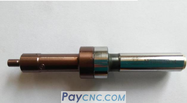
This is an eccentric edge finder, which determines the spindle center by looking for a coaxial rotation point close to the edge of the workpiece. Of course, it should be noted that when the point after the edge finder is on the same axis, it is 5 mm away from the position we need by a radius, so pay attention to it when calculating.
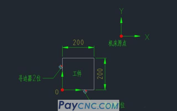
The figure above shows the position of the workpiece on the machine tool. Let's first place the edge finder on the edge finder as shown in the picture, and record the current Y-axis mechanical coordinate position a, and the value entered in the G54 coordinate system Is a+5. Then place the edge finder at the 2 position shown in the picture, and record the current X-axis mechanical coordinate position b. The value entered in the G54 coordinate system is b+5. Add when the desired position is away from the measuring point along the positive direction of the axis, and reduce it otherwise.
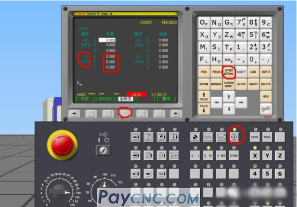
The specific interface operation is shown in the figure above. Set the machine tool to the handwheel mode, move the sliding table to the desired position, press the offset setting button (offset setting), find the coordinate system, the interface displays XYZ of the G54 coordinate system, we Enter the XY mechanical coordinate positions one by one according to the previous method. The input key button is input. As a result, the coordinate system of the XY plane has been completed. For the Z axis, because of the relationship between the length of the tool, if we use more than 2 tools for each processing, we cannot directly input it on the Z axis. We need to set it in the tool offset.
|
 |
| Products Catalogue | Home | About Us | Retrofit | Download | News | Tech Support | Contact Us | |
|
|
|