 01application environment
For machine tool spindles with non-1:1 transmission, only the motor encoder cannot achieve the spindle orientation, and when the spindle orientation accuracy is not high, you can install a proximity switch on the spindle to replace the spindle encoder, using the signal of the induction switch as Orientation reference point signal for spindle orientation or speed/position switching function to realize tool change, tapping or thread processing. In this way, a high-precision position control function can be realized while being convenient and reducing costs.
02Basic parameter requirements of inductive switches and driver version requirements
1. Inductive switch parameter requirements
Type: NPN type
Power supply voltage: DC 24V
Induction frequency: recommended greater than 1KHZ
2. Driver version requirements
GR series: V5.20 and above
GS-N series: (+ version common to synchronous and asynchronous machines)
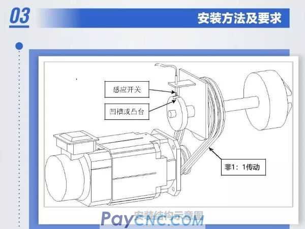 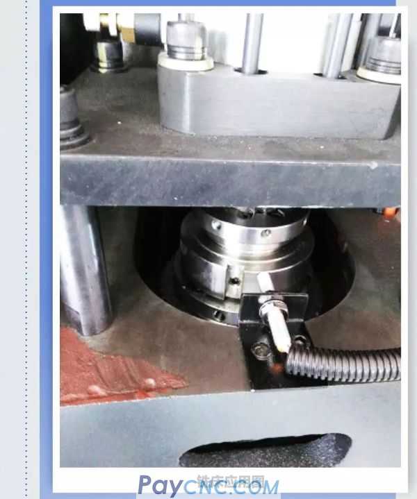 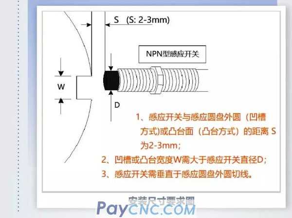 
03Installation method and requirements
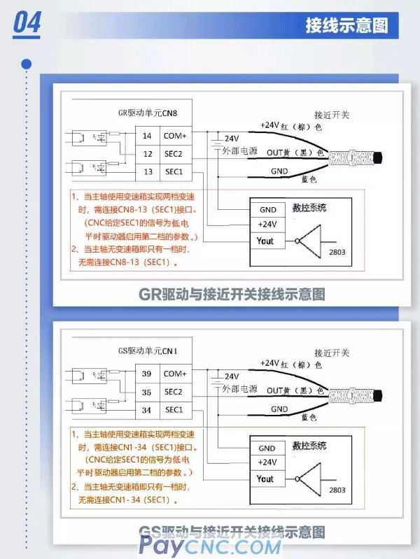
04 Wiring diagram
05 debugging method
1. The first parameter setting of orientation function
Pa97=2 Select inductive switch as directional feedback signal.
Pa154 First gear mechanical magnification (The value of the mechanical gear ratio between the spindle end and the motor end is filled in this parameter with a value of 1000. For example, the main shaft gear has 40 teeth, the motor gear has 38 teeth, that is, 40/38*1000~1053, fill in 1053 Input parameter PA154)
PA152=2 is recommended to be 2
(Orientation change mode=0 direct orientation, that is, the orientation can be completed within one circle;=2 during orientation, find two zero points to compare the previous zero point value, and then make orientation)
PA100=1/2 is recommended to be set to 1 or 2, that is to fix one direction (orientation direction selection: =0 current motor rotation direction (when running) or the direction of the closest distance (when stopped); =1 forward CCW direction; =2 Reverse CW direction)
Pa103 first gear exact stop position low
(Setting method: After receiving the position where the spindle needs to be switched or orientated, the position of the spindle encoder "DP-SPO" and the value of "DP-SPO" "thousands" and the following four digits are filled into PA103 ; "Ten thousand" digits and above are filled in PA104.
Note: 1 The unit of the lowest digit of "DP-SPO" is "100,000"; 2. The five digits of "DP-SPO" are "10,000", "thousand", "hundred" and "ten". When several digits in sequence are zero, the corresponding digits do not display any numbers. In fact, the corresponding value is "0", so "DP-SPO" must be combined to calculate the encoder position value)
Pa104 first gear exact stop position high
Pa99 first gear orientation speed (the default value is 100, if the transmission is relatively large, this parameter may need to be set larger to avoid the alarm for too long orientation time)
Pa153 detects the signal deviation range of the two induction edges (unit 0.06 degrees, generally the default value is sufficient, if the mechanical gap is large or the transmission ratio differs greatly from the actual value, it needs to be set larger)
PA102 positioning window (unit 0.01 degree, generally use the default value, if the mechanical gap is large, it may need to be set larger)
2. The second parameter setting of the orientation function
Pa155 second gear mechanical override (setting method is the same as PA154)
Pa105 second gear exact stop position low (setting method is the same as PA103)
Pa106 second gear exact stop position high (setting method is the same as PA104)
Pa159 second gear directional speed
3. C/S switch function parameter setting
PA88=0/1=0 to find the reference point; =1 to not find the reference point (this parameter is related to the C/S switching function and not related to "Spindle Exact Stop" M51, that is, "Spindle Exact Stop" does not need to set this parameter )
PA90C/S switch position low (setting method is the same as PA103)
PA91C/S switch position high (the setting method is the same as PA104)
Debugging points
It is necessary to rotate the spindle at least 3 revolutions. When the value displayed by DP-SPO changes from "E" to t0000 (the zero signal (ie the sensor switch signal) is triggered), the value after the letter "t" is the valid value. As a reference value for the orientation function
The maximum value displayed by DP-SPO is the number of virtual spindle encoder lines, and the value of the target angle position to be oriented can also be calculated according to the number of spindle encoder lines. (The number of spindle encoder lines is equal to the number of motor encoder lines 4 times the frequency and then multiplied by the mechanical gear ratio. For example, the number of motor encoder lines is 5000 lines, the main shaft gear is 40 teeth, and the motor gear is 38 teeth. Then, the number of spindle encoder lines =5000*4*40*38=21053)
Through the driver input and output status monitoring window (GR series are DL-in, DL-out; GS-N series are DP-in, DP-out), it is convenient to verify the "zero" point signal of the sensor switch and the input signal of the host computer to the driver And the output signal status of the driver
The input command DL-IN sent by the CNC system to the servo unit is as follows:
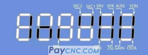
SEC2: It flashes every time the spindle rotates to prove that the "zero" point of the sensor switch is valid.
SEC1: when it is lit, the second gear is enabled
OSTA: Directional start signal input
PSTI: Speed position switch input
SON: Enable signal. Both orientation and speed position switching must have this signal at the same time
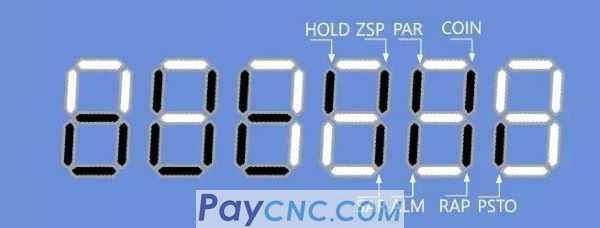
The output command DL-OUT sent by the servo unit to the CNC system is as follows
COIN: directed completion output
PSTO: Speed position switch complete output
Common troubleshooting methods
System alarm "positioning time is too long"; system parameter "positioning alarm time" is set too small, it is recommended to set as large as possible
ERR-25 (orientation failure alarm)
1. There is no sensor switch signal (the corresponding picture in the display window "SEC2" of rotating the spindle is not flashing)
a Wrong sensor switch model (not NPN type)
b Incorrect wiring
c Sensor switch installation distance is not suitable
2. PA154 (PA155) caused by incorrect setting of mechanical magnification; set correctly.
3. Too much deceleration ratio makes the actual orientation speed too slow, resulting in orientation timeout; increase the setting value of PA99 (PA159).
4. The orientation time is not enough; increase the PA142 orientation failure alarm time
5. The induction slot is too narrow, resulting in insufficient induction signal time; adjust the induction slot width as required to be larger than the diameter of the induction switch
6. Due to the large mechanical gap, the positioning deviation will be large, and the positioning window setting is relatively small, resulting in occasionally unsuccessful positioning; appropriately increase the PA102 setting value
7. Due to the large mechanical gap, and the allowable value of PA153's two-time change tolerance is too small, the change will occasionally fail; appropriately increase the setting value of PA153.
8. Multiple signals are sensed when the spindle rotates once ("SEC2" flashes several times): It may be caused by the similar extra screw protrusions on the induction plate
Spindle jitter during orientation: the rigidity is not suitable, please increase PA48, decrease PA49, and decrease PA23 appropriately
Orientation is successful, but the position deviation of repeated positioning is large
1. Due to the large mechanical backlash, the orientation direction is not fixed to the same direction: set PA152=2; PA100=1 (1 or 2)
(Set the change method to repeat the search twice; set the orientation direction to a fixed direction to avoid reverse mechanical backlash)
2. The operating speed of the spindle before orientation is too different from the orientation speed (and the transmission belt is loose or the mechanical gap is large); let the spindle reduce the speed before giving the orientation or set the orientation speed to the speed before orientation
|
 |
| Products Catalogue | Home | About Us | Retrofit | Download | News | Tech Support | Contact Us | |
|
|
|