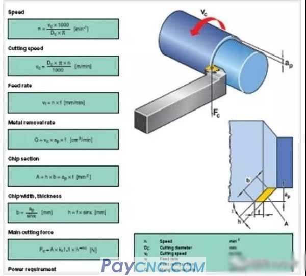
01 Three Elements of Cutting
1. Linear velocity Vc
The length of the blade moving on the machined surface of the workpiece per minute. Representation unit: m/min. The specific performance of the linear speed in the cutting process is mainly the spindle speed.
The conversion formula is: S=VcX1000/3.14D
D: Cutting diameter of the workpiece to be processed
2. Depth of cut ap
The distance from the surface of the workpiece to be processed to the surface of the processed workpiece, expressed in mm.
3. Feed amount F
The distance that the workpiece moves in the cutting direction for each rotation of the workpiece, expressed in mm/r.
CNC lathe programming, how to set the turning parameters? How to determine the line speed Vc, cutting depth ap, feed rate F? Technical Digest Sheet 1
CNC lathe programming, how to set the turning parameters? How to determine the line speed Vc, cutting depth ap, feed rate F?

n —speed, r/min
Vc—cutting speed, m/min
d —milling cutter diameter, mm
f —feed rate, mm/r
Z---tooth number
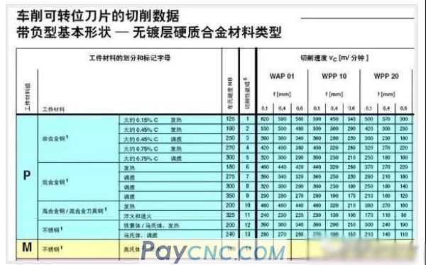
02 Determination of line speed
After the blade is selected, the line speed can be preliminarily determined according to the simple tool parameter table provided by the company:
03 Cutting speed Vc
1. Cutting speed has a great influence on tool durability. Increasing cutting speed can shorten processing time and improve processing efficiency. However, if the line speed is too high, the cutting temperature will rise and the tool durability will be greatly shortened. Each company's tool life has a specific time. Generally, when processing at the line speed specified by the company's sample, each edge is processed for 15-20 minutes to reach the life. If the linear velocity is higher than 20% of the specified linear velocity in the sample, the tool life will be reduced to 1/2 of the original; if it is increased to 50%, the tool life will be only 1/5 of the original.
2. When machining at low cutting speed (cutting speed 20-40m/min), the workpiece is prone to vibration and the tool durability is also low.
3. If the hardness of the same material is high, the cutting speed should decrease; if the hardness is low, the cutting speed should increase.
4. The cutting speed increases, and the surface roughness is good; the cutting speed decreases, and the surface roughness is poor.
Example: The material of a certain upper cover is 45# steel, quenched and tempered hardness HRC28-32. The rotation speed used when processing the M105X2 thread is 800 rpm. At present, each cutting edge of the thread cutter can only process 8-10 workpieces.
The main reason: the line speed is too high and the tool life is greatly reduced. The current linear velocity of the tool is Vc=3.14X800/1000=251.2m/min. If processing according to the 45# steel non-modulated parts, the tool linear speed should be 180-200m/min, and if it is modulated to HRC28-32, the linear speed should be reduced to about 120m/min for processing. Among them, the influence caused by the large pitch and the large cutting force during processing is taken into consideration.
04 cut depth ap
The depth of cut is determined according to the allowance, shape, machine power, rigidity and tool rigidity of the workpiece. The change in depth of cut has a great influence on tool life.
1. If the cutting depth is too large, the cutting force exceeds the endurance of the cutting edge, resulting in chipping and scrapping of the cutting edge;
2. The cutting depth is too small. When the cutting depth is small, the tool does not perform normal cutting, but scratches on the surface of the workpiece, resulting in a hardened layer during cutting, which is the reason for the reduction of tool durability and poor surface roughness of the workpiece;
3. When cutting the cast iron surface and the black surface layer, the cutting depth should be increased as much as possible under the condition of the machine power permitting, otherwise the cutting edge tip will be chipped and abnormally worn due to the cutting surface hardened layer of the workpiece. . For example, when peeling and turning a hot-rolled D80 round steel piece, assuming that the round steel piece due to the ellipse causes the maximum and minimum external dimensions to be 82 and 78, respectively, the first cutting depth must be less than 78. Since the tool tip has been continuously processed, it can effectively ensure that the tool tip does not chip, thereby increasing the service life of the tool.
4. For workpieces of different materials or workpieces of the same material but with different heat treatment hardness, the depth of cut during processing will be different, which should be determined according to the actual situation.
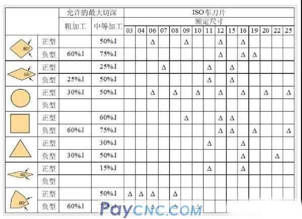
5. Experience effective cutting edge length:
C-type blade: 2/3*blade length l
W-shaped blade: 1/4*blade length l
V-shaped blade: 1/4*blade length l
T-type blade: 1/2*blade length l
D-type blade: 1/2*blade length l
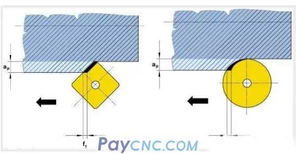
05 Blade shape and size, cutting depth
06 Feed
1. In the turning process, each time the workpiece rotates, the amount of advancement of the turning tool is the feed amount.
2. The amount of feed has a great relationship with the surface roughness of the machined surface, and the feed is usually determined according to the requirements of the surface roughness
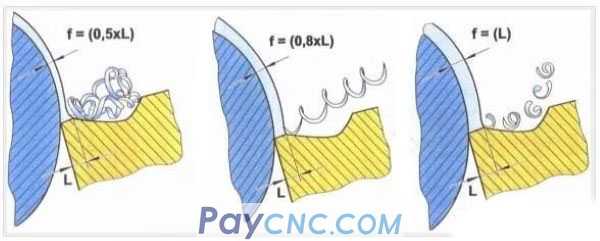
1) The feed amount should be greater than the chamfering width, otherwise the chip can not be broken, generally take about twice the chamfering width
2) The feed rate is large, the thickness of the chip layer increases, and the cutting force increases
3) The feed rate is large, correspondingly requires a larger cutting power
3. The influence of feed
1) The feed rate is small, the back wear is large, and the tool durability is quickly reduced
2) The feed rate is large, the cutting temperature rises, and the flank wear increases, but it has a smaller impact on the tool durability than the cutting speed
3) Large feed rate and high processing efficiency
4) The feed amount is between 0.1-0.4, which has little influence on the flank face, depending on the specific situation. Empirical formula f thick = 0.5 * tool nose radius
07 The relationship between cutting parameters and chip breaking
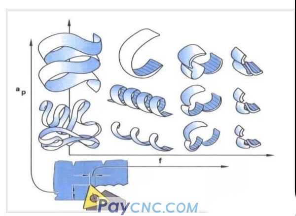
The relationship between chip breaking and feed and chamfer width:
 |
 |
| Products Catalogue | Home | About Us | Retrofit | Download | News | Tech Support | Contact Us | |
|
|
|