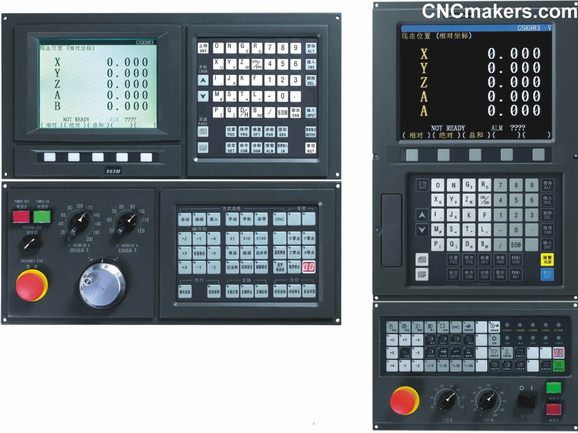
GSK983M CNC Milling Controller
GSK983M includes GSK983M-S,GSK983M-H,GSK983M-V and GSK983MA-H from CNCmakers, with high cost-performance and high reliable CNC developed especially for high speed, high precision and high efficient machining. Due to the applied high speed micro processor and high speed and precision servo system as well as sufficient CNC and high speed PLC functions, the machining efficiency has truly realized a higher standard.
High precision machining
The high precision and high resonance position control has been realized by high performance position closed loop control chip and high precision position detecting components.
The mechanical errors in transmission chains such as pitch error of ball screw can be remedied by pitch memory error compensation.
Feedrate override can be automatically adjusted in the corner contour machining.
High speed machining
When the system resolution is 1?, the highest feedrate can reach 240m /min which is suitable for the control of milling press, MCs, engraving machines and super precision machine tools. The continuous high speed machining of micro block is realized by the distributed processing of multi-high speed CPU. The super processing capability of 1000 instruction words per second is especially suitable for the machining of high speed mould, auto parts and the control of woodworkers and laser machines.
High speed DNC functions
The specially developed high speed DNC buffer interface realizes the high speed DNC machining by the connection to PC or U disk at the baud rate as high as 115200 .
Sufficient control functions
It has the functions of maximum 5 feeding axes plus 1 spindle control, cutting tools life management, scaling, coordinate system rotation, complex canned cycle, background editing, graphics display and special user macro program that can easily carry out some special machining.
Powerful built-in PLC
The built-in sequence control for machine and the large PLC capacity for peripherals have greatly simplified the strong power design.
PLC-A 2000 steps PLC-B 12000 steps
Smart CNC
It adopts the latest high integral FPGA, CPLD chips and surface sticking adornment techniques which greatly reduces the dimensions of the control unit. And the LCD displayer adopted realizes the thin model of display unit.
Module I/O
The module design adopts I/O unit which can be paralleled by requirement with maximum (input/output) points are 192/128. It can be fixed on the standard DIN rail to directly drive the load such as contactor, which makes the strong power design much simple and the space taken up is much more reduced.
The wires from CNC to strong power plate are much more saved through the connection of the high speed serial communication ports with CNC.
The machine operation panel
It has maximum 64 mechanical keys with a LED indicator for each. Their function specified by PLC programming and also they can correspondingly connect the switches of feedrate override, spindle override, MPG override and coordinate axis.
Separating structure:
Connect CNC by the high speed serial communication ports to save the wire.
|
NC function
|
|
Controlled axis
|
Controlled, link axis: up to 5 feeding axes, 1 spindle, and 4 axes to link
|
|
Interpolation method: linear(G01) , circular (G02, G03), sine(G07)
|
|
Max. stroke: metric: 99999.999mm inch :9999.9999inch
|
|
Setting increment
|
Least input increment 0.001mm /metric 0.0001inch/inch
|
|
Least increment : X axis : 0.001mm / metric 0.0001inch/ inch
Y axis : 0.001mm / metric 0.0001inch/ inch
Z axis : 0.001mm / metric 0.0001inch/ inch |
|
Max. traverse rate
|
240 , 000mm /min or 9 , 600inch/min
|
|
Max. feedrate
|
G94 : 150,000mm /min or 60 , 000.00inch /min
|
|
G95: 2 , 000.00mm /r or 200.0000inch/r
|
|
Automatic acceleration/deceleration: Execute the linear acceleration/deceleration to shorten the positioning time when automatically rapid feeding in Jog or Auto mode
|
|
Automatic acceleration/deceleration in cutting feed: automatic acceleration/ deceleration for cutting feed or manual continuous feed index, parameter setting the time constant from 8ms to 4000ms.
|
|
Buffer register: advance to read the instructions of the following two blocks to eliminate the interruption of NC instruction caused by reading the instructions to improve the working efficiency.
|
|
MSTB function
|
Tool function T : • T2 digit/T4 digit • 99 groups tool offset • tool position offset ?tool length compensation
|
|
• tool radius compensation B/C • communication input of tool offset value
• tool length measure • tool life management |
|
Spindle function S : • S2 digit/ S4 digit A(12 digit BCD output /analog output) • S4 digit B(12 digit BCD output/analog output )( 4-grade gear input ) • max. spindle speed limit.
|
|
auxiliary function M : specified by the sequential 2 digits after address M. End
of program : M02 • M30 , program stop : M00 , optional stop : M01 , subprogram call : M98 , end of subprogram : M99. Other M functions can exclusively be defined by user. |
|
The second auxiliary function B: it is specified by the sequential 3 digitals behind B,
BCD signal of the three digitals are transmitted to the machine side.
|
|
The function is used for the positioning of graduation worktable.
|
|
Precision compensation
|
?stored pitch error compensation: compensate the error caused by machine position to improve the processing precision and the compensated data is stored to the memory.
|
|
?backlash compensation: compensating the loss momentum of machine
|
|
Tool length compensation and tool nose radius compensation : the tool length is specified by G codes ( G43 , G44 , G49 ) .
|
|
• tool nose radius compensation (G40 , G41 , G42), the compensation value for every tool is stored to the memory.
|
|
Max. compensation value: ? 999.999mm or ?99.9999inch.
|
|
Reliability and safety
|
• emergency stop ; • overtravel ; • stored stroke limit ; • NC ready signal ; • servo ready signal ; • MST functional completion signal ; • starting signal in automatic run ; • signal in automatic run ; • feed hold indicator signal ; • safety door interlock ;
|
|
NC alarm : • program error and operation error ; • overtravel error ; • servo system error ; • connection error, MDI data transmission error between, PMC error ; • memory ( ROM and RAM ) error ;
More than 300 alarm numbers to the stable operation and troubleshooting for the system. |
|
Self-diagnosis: check the followings : • system abnormity ; • position control abnormity ; • servo system abnormity ; • CPU abnormity ; • ROM abnormity ; • RAM abnormity ; • MDI/machine operation panel data transmission ; • RS232 read abnormity ; • PC data transmission abnormity ; and so on.
|
|
Operation
|
• dry run • interlock • single block • optional skip block • manual absolute value ON/OFF • auxiliary function lock(M. S.T lock)
• machine lock • feed hold • cycle start • overtravel release • emergence stop • external reset signal • external power supply ON/OFF • manual continuous feed • incremental feed • MPG • skip • additional optional block skip • rapid feed overshoot • manual insertion function • sequence number search • program number search • external workpiece number research • external data input • sequential number comparison stop • program start again • menu switch • graph display • external position display |
|
Display
|
• 7.5inch 640 • 480 homochrome LCD screen ?machine coordinates, absolute coordinate, incremental coordinate, distance to move
|
|
• user program • current operation mode • system parameter, diagnosis number, alarm number, macro variable value, tool offset setting, MDI command, MST
|
|
State • actual federate, spindle speed • machining path graph
|
|
• Run time and other NC instructions and state information
|
|
PMC function
|
Control method : cycle running; run speed:30us/step for basic instruction
|
|
Input/output : 192/128 ; 5000 steps
|
|
Development method: PMC instruction or ladder diagram
|
|
Instruction amount: 34 including 12 basic instructions and 22 function instructions
|
|
DNC function
|
Serial DNC to connect U disc
|
|
Table 2.13 G code list
|
|
G codes
|
Group
|
Function
|
|
G00
|
01
|
Positioning
|
|
G01
|
Linear interpolation
|
|
G02
|
Circular interpolation (CW)
|
|
G03
|
Circular interpolation (CCW)
|
|
G04
|
00
|
Dwell
|
|
G05
|
High-speed continuous cutting mode
|
|
G07
|
Federate sine curve control
|
|
G09
|
00
|
Exact stop check
|
|
G10
|
Offset value setting, start of registration of tool life management data
|
|
G11
|
00
|
End of registration of tool life management data
|
|
G17
|
02
|
XY plane selection
|
|
G18
|
ZX plane selection
|
|
G19
|
YZ plane selection
|
|
G20
|
06
|
Input in inch
|
|
G21
|
Input in mm
|
|
G22
|
04
|
Stored stroke limit ON
|
|
G23
|
Stored stroke limit OFF
|
|
G27
|
00
|
Reference point return check
|
|
G28
|
Return to reference point
|
|
G29
|
Return from reference point
|
|
G30
|
Return to 2 nd , 3 rd , 4 th reference point
|
|
G31
|
Skipping cutting
|
|
G33
|
01
|
Thread cutting
|
|
G40
|
07
|
Cutter compensation cancel
|
|
G41
|
Cutter compensation left
|
|
G42
|
Cutter compensation right
|
|
G43
|
08
|
Tool length compensation + direction
|
|
G44
|
Tool length compensation - direction
|
|
G49
|
Tool length compensation cancel
|
|
G45
|
00
|
Tool offset increase
|
|
G46
|
Tool offset decrease
|
|
G47
|
Tool offset double increase
|
|
G48
|
Tool offset double decrease
|
|
G50
|
11
|
Scaling off
|
|
G51
|
Scaling on
|
|
G54
|
12
|
Workpiece coordinate system 1 select
|
|
G55
|
Workpiece coordinate system 2 select
|
|
G56
|
Workpiece coordinate system 3 select
|
|
G57
|
Workpiece coordinate system 4 select
|
|
G58
|
Workpiece coordinate system 5 select
|
|
G59
|
Workpiece coordinate system 6 select
|
|
G60
|
00
|
Single directional positioning
|
|
G61
|
Exact stop check mode
|
|
G62
|
13
|
Automatic corner override
|
|
G64
|
Cutting mode
|
|
G65
|
00
|
Custom macro simple call
|
|
G66
|
14
|
Custom macro modal call
|
|
G67
|
Custom macro modal call cancellation
|
|
G73
|
09
|
Peck drilling cycle
|
|
G74
|
Counter tapping cycle
|
|
G76
|
Fine boring
|
|
G80
|
Canned cycle cancel
|
|
G81
|
Drilling cycle, spot boring
|
|
G82
|
Drilling cycle, counter boring
|
|
G83
|
Peck drilling cycle
|
|
G84
|
Tapping cycle
|
|
G85
|
Boring cycle
|
|
G86
|
Boring cycle
|
|
G87
|
Back boring cycle
|
|
G88
|
Boring cycle
|
|
G89
|
Boring cycle
|
|
G90
|
03
|
Absolute programming
|
|
G91
|
Incremental programming
|
|
G92
|
00
|
Absolute zero programming
|
|
G94
|
05
|
Per minute feed
|
|
G95
|
Per revolution feed
|
|
G98
|
10
|
Return to initial point in canned cycle
|
|
G99
|
Return to R point in canned cycle
|
User Manual of GSK983M:
 GSK983M_CNC_SYSTEM_USER_MANUAL.rar GSK983M_CNC_SYSTEM_USER_MANUAL.rar
PLC Manual of GSK983M:
GSK983M(T)_CNC_Milling_Machine_Controller_PLC_Program_Manual.rar
GSK983M-H Connection Manual:
GSK983M-H_M-VM-V21_CNC_Milling_Machine_Controller_Connection_Manual.rar
GSK983M-V Connection Manual:
GSK983M-V_CNC_Milling_Machine_Controller_Connection_Manual.rar
GSK983M-S Connection Manual:
GSK983M-S_CNC_Milling_Machine_Controller_Connection_Manual.rar
CNC Retrofit Kit
|