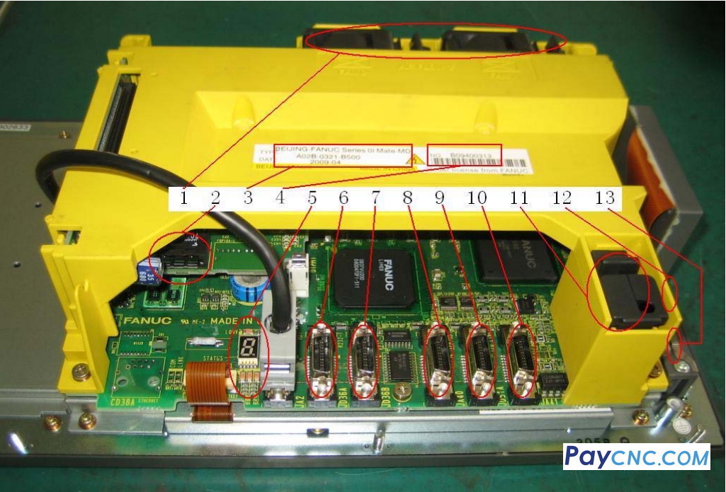
FANUC 0iD CNC interface
The corresponding explanation of each part in the above picture: 1. System fan. If the system fan fails, the system will have an alarm of "701 fan". This alarm can be shielded by setting parameter 8901#0 to 1. However, for the safe use of the system, please replace the fan as soon as possible.
2. Optical cable plug COP10A. Data communication between the system axis card and the servo amplifier.
3. The 9-digit system serial number is written after NO. (the number purchased from Beijing FANUC starts with B, and the number imported from overseas starts with E, such as: B09400313). Each system has a unique serial number.
4. The type of system is written after TYPE, such as: 0i-Mate-MD A02B-0321-B500.
5. The indicator light on the system motherboard. The fault part of the system can be judged according to the status of these alarm lights.
6. Plug JD36A. RS232 serial interface, channel 1.
7. Plug JD36B. RS232 serial interface, channel 2.
8. Plug JA40. Spindle analog output/high-speed DI point input port. If the machine tool does not use FANUC spindle motor and amplifier but uses inverter to control the spindle, this interface provides 0-10V analog control voltage to the inverter output.
9. Plug JD1A. I/O LINK interface, through which the system communicates with the I/O device of the machine tool power cabinet (including the machine tool operation panel) and exchanges I/O numbers.
10. Plug JA7A. It is the connection port of the serial spindle. If the FANUC spindle amplifier is used, this interface is connected to the interface JA7B on the spindle amplifier.
11. System battery. It is used to maintain the data in the system SRAM when the machine tool is shut down. If the battery is dead, the system SRAM will lose its stored information, and system alarms such as #935 will appear, causing the machine tool to fail to start normally. When the system prompts "BAT", back up the system data and replace the battery as soon as possible.
12. The fuse on the system. If the fuse is blown, the system will not start (the fuse is blocked in this picture, but its physical location is shown in the picture).
13. Plug CP1. The input of the DC24V power supply of the system. If the system screen is black when the machine tool is turned on, first check whether there is a DC24V power input here. If the DC24V power input is normal, check the system fuse of item "12". Note that this DC24V must use a 24V regulated power supply. |
