High and low gear are generally divided into: ZF gear high and low gear, ordinary hydraulic high and low gear.
The difference between the two: ZF gear high and low gear, after shifting to high or low gear, the output coil is not maintained; after ordinary hydraulic high and low gear shifting to high or low gear, the output coil remains. In the process of tool shifting, the ZF high and low gear spindle clockwise and reversing time is set to 128ms, and the ordinary low gear spindle clockwise and reversing time is set to 3000ms, that is, when the ordinary high and low gear rotates in one direction, the gear is changed.
1. Debugging method of FANUC system high and low.
Related parameters:
3705#2: Gear switching mode
3732: The speed of the spindle motor when the spindle gear is displaced
3735: Minimum clamping speed of spindle motor
3736: Maximum clamping speed of spindle motor
3741: Maximum spindle speed corresponding to gear 1
3742: Maximum spindle speed corresponding to gear 2
3751: Spindle motor speed at the switching point of gear 1-gear 2
3752: Spindle motor speed at the switching point of gear 2-gear 3
4056-4059: Gear ratio data between spindle and motor
4171-4174: Gear ratio data between motor sensor and main shaft
Example 1: ZF gear ratio is 1:1 for high gear and 4:1 for low gear. The shift speed is 800 and the maximum speed of the spindle motor is 7000.
Problem solving:
Parameter 3705#2=1
Parameter 3732 set 3
Parameter 3735 set 5
Parameter 3736=4095
Parameter 3741=7000/4=1750
Parameter 3742=7000
Parameter 3751=[800(shift speed)X4095(parameter 3752)]/[1750(parameter 3741)]=1872
Parameter 3752=4095
Parameters 4056-4059 are set to 100, 100, 100, 400,
Set parameters 4171-4174 to 1, 1, 4, 1 respectively
Example 2, ordinary hydraulic high and low gear, high gear ratio 1:0.875, low gear ratio 1:0.230263, required shift speed 1000, spindle motor maximum speed 7000
Problem solving:
High-grade ratio 1:0.875=8/7=114/100, low-grade ratio 1:0.230263=434/100/=5472/1260
Parameter 3705#2=1
Parameter 3732 set 3
Parameter 3735 set 5
Parameter 3736=4095
Parameter 3741=7000/4.342=1612
Parameter 3742=7000X(7/8) (high-grade ratio)=6125
Parameter 3751=[1000(shift speed)X4095(parameter 3752)/1612(parameter 3741)]=2540
Parameter 3752=4095
The parameters 4056-4059 are respectively set 114, 100, 434, 100,
Parameters 4171-4174 are set to 8, 7, 5472, 1260
Example 3, ordinary hydraulic high and low gear, high gear ratio 1:1.357, low gear ratio 4.873:1 requires a gear shift speed of 1000, a maximum spindle motor speed of 8000, and a maximum spindle speed of 4500
Parameter 3705#2=1
Parameter 3732 set 3
Parameter 3735 set 5
Parameter 3736=4095
Parameter 3741=[Parameter 3742(6106)]/4.873=1253
Parameter 3742=4500X1.357 (high-grade ratio)=6106 is less than 8000
Parameter 3751=[1000(shift speed)X4095(parameter 3752)]/[1253(parameter 3741)]=3268
Parameter 3752=4095
The parameters 4056-4059 are respectively set to 1000, 1357, 1000, 4873,
The parameters 4171-4174 are set to 1357, 1000, 4873, 1000 respectively
2. Mitsubishi system high and low level debugging method.
Related parameters:
3023 minimum spindle speed clamp
3001-3004 limit speed
3005-3008 maximum speed
13057-13060 main shaft gear ratio 1
13061-13064 Motor gear ratio 1
Example 1, ZF gear ratio is 1:1 for high gear and 4:1 for low gear. The gear shift speed is 1500 and the maximum speed of the spindle motor is 6000.
Problem solving:
Parameter 3023=3
Parameter 3001=1500
Parameter 3001=1500
Parameters 3006-3008=6000
Parameter 13057=4
Parameters 13058-13064=1
Example 2, ordinary hydraulic high and low gear, high gear, high gear 1: 0.875, low gear, 1: 0.230263, gear shift speed is required to be 1000, and the maximum speed of spindle motor is 6000
Problem solving:
Parameter 3023=3
Parameter 3001=1000
Parameter 3002-3004=6000
Parameter 3005=1000
Parameters 3006-3008=6000
Parameter 13057=5472
Parameter 13058=8
Parameter 13058-13059=1
Parameter 13061=1260
Parameter 13062=7
Parameters 13063-13064=1
3. Debugging steps
First of all, judge whether the spindle position is high or low, and the corresponding signal is correct. Generally, the high and low gears require much less force to rotate by hand than the low gear. High and low gears require at least 1NC 1NO relay.
Rotate the spindle after confirming that the signal and connection are all right.
In MDI mode, input S speed, and if there is no M3 or M4, whether the gear shift is normal. To shift gears, the spindle needs to be shifted at a rotation speed of 3-5 positive and negative swings. The swing speed is different from the ZF gear high and low gears & ordinary high and low gears.
If the high and low gears are switched normally, the normal speed S plus M3 or M4 can be used to shift gears. Pay attention to smooth gear shifting, no problem at high speed and high speed test once the sound is heard, high-speed long-term rotation is prohibited. It is forbidden to rotate high and low gears without oil.
4. FANUC with external spindle orientation function:
1) Initial orientation, 445 is not displayed in the diagnosis
(1) Perform a spindle rotation after starting up, such as: M3S500, then execute M19 to check whether the diagnosis 445 parameter changes
(2) If the diagnosis parameter 445 is always 0, check whether the NC parameter 3117#1 is 1
(3) If the diagnosis parameter 445 becomes 0 after pressing the reset button, check whether the NC parameter 4016#7 is 0
(4) Just fill in a value in 4077, and perform M19 orientation, and then check whether there is a value in the diagnostic parameter 445
2) The spindle cannot be oriented
Re-fill in the motor code and initialize with 4019#7=1, shut down and restart; the maximum speed of the spindle motor is 4020,4001#4 is 1,4002#0 is 1; re-orientation
3) When the spindle is in a certain direction, it will report the error of 1 revolution signal of the sensor on the SP9081 (S) motor
Check whether the high and low electronic gear ratio is wrong
4) The disc tool magazine exchanges tools repeatedly to ensure that the spindle rotates and positions every time a tool is exchanged
1604#0 is 1
4016#7 changed to 1
4075 (positioning error) changed from 10 to 20
In addition, 4016#7 is set to 1, to avoid rotating the spindle to reposition when the spindle is high-end, the positioning will be inaccurate
5) Parameter 4003#3 is 1, the spindle defaults to forward rotation orientation
When there is an external positioning switch, 4003#3 is 0, first rotate forward and then orientation, forward orientation, first reverse then orientation, reverse orientation, there is a certain deviation in the middle, change to 1, all are positive orientation; no With external directional switch, whether it is 1 or not has no effect
6) Parameter 4006#1 is 1, spindle high and low gear orientation speed
4006#1 is set to 1, otherwise the positioning signal will not be found if the spindle is oriented too fast. It is mainly for high-end, and it will keep rotating during orientation. It is recommended not to use too slow rotation speed. It is better to use parameter 4038 spindle orientation speed to handle it.
7) Other commonly used spindle orientation related parameters
3705#1GST uses spindle orientation signal G29.5, 0 for orientation, 1 for gear switching
3732 Spindle speed during spindle orientation or spindle motor speed during spindle gear displacement. When 3705#1=0, set the spindle speed when the spindle is oriented in units of /min; when 3705#1=1, set the spindle motor speed when the spindle gear is displaced according to the following formula, and set the value when the spindle is serialized =16383 multiplied by the spindle motor speed when the spindle gear is displaced and then divided by the maximum speed of the spindle motor. When the spindle is simulated, the set value = 4095 multiplied by the spindle motor speed when the spindle gear is displaced and divided by the maximum speed of the spindle motor
4000#0 The rotation direction of the main shaft and the motor, 0 is the same, 1 is the opposite
4002#3,2,1,0 Use the sensor of the motor for position feedback, when using an external one-turn signal, set 0.0.0.1
4004#2 Use external one-turn signal, set 1
4004#3 External switch signal type, set according to the meter debugging manual, use the company's directional switch to set 1
4010#2,1,0 Set the type of motor sensor, set 0.0.1
4011#2,1,0 Motor sensor tooth number, initialized and automatically set
4015#0 Directional valid, set to 1
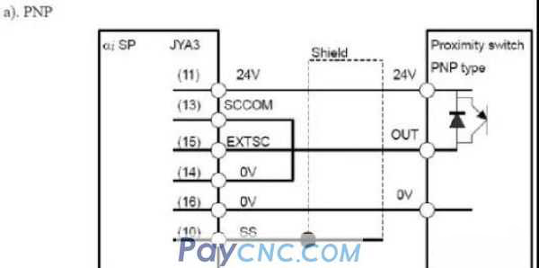
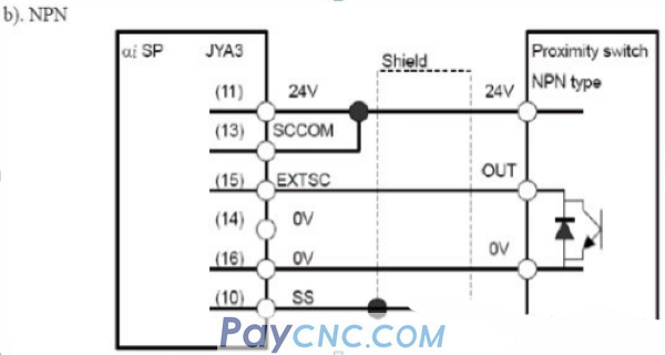
8) Spindle orientation PNP external orientation connection mode
  |
 |
| Products Catalogue | Home | About Us | Retrofit | Download | News | Tech Support | Contact Us | |
|
|
|
