Fanuc Servo Amplifier Fault Solution
Feed servo system fault handling

There are about three types of fault alarm phenomena in the feed servo system: one is to use the software diagnostic program to display the alarm information on the CRT; the second is to use the hardware on the servo system (such as light-emitting diodes, fuses, etc.) to display the alarm; the third is the fault without any alarm display
Picture
1) Software alarm form
(1) Servo feed system error alarm This type of alarm is mostly caused by a fault in the speed control unit or a fault in the main control printed circuit board related to position control or servo signals.
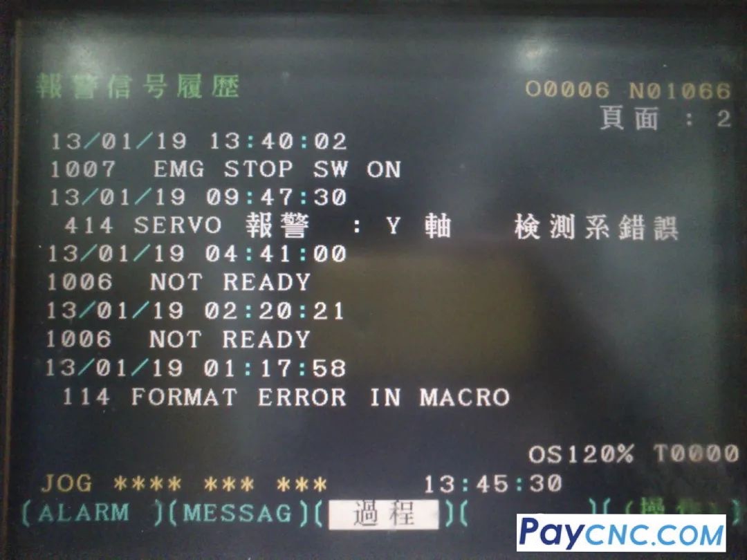
(2) Detection error alarm It refers to a fault caused by the detection element (tachometer generator, rotary transformer or pulse encoder) or the detection signal.
(3) Overheating alarm The overheating mentioned here refers to the overheating of the servo unit, transformer and servo motor.
In short, according to the alarm signal displayed on the CRT and the prompts of the causes of various alarm information in the machine tool maintenance manual, the fault can be analyzed and judged to find out and eliminate it.
2) Hardware alarm form
(1) High current alarm In this case, the power drive element (thyristor module or transistor module) on the speed control unit is mostly damaged. During the inspection, cut off the power supply and use a multimeter to measure the resistance between the collector and emitter of the module. If it is less than or equal to 10 ohms, it indicates that the module is damaged.
(2) High voltage alarm The reason for this alarm is that the input AC power voltage exceeds 10% of the rated value, or the insulation capacity of the motor is reduced, or the printed circuit board of the speed control unit is defective.
(3) Low voltage alarm Most of the time, it is caused by the input voltage being lower than 85% of the rated value, or the power connection is poor, or the printed circuit board of the servo unit is faulty.
(4) Speed feedback line alarm This alarm is mostly caused by poor speed or position feedback line of the servo motor or poor contact of the connector.
(5) Overload alarm The reason may be abnormal mechanical load, which can be determined by measuring the motor with an oscilloscope or ammeter; or the upper limit of the motor current on the speed control unit is set too low or the permanent magnet on the permanent magnet motor falls off, or the printed circuit board of the servo unit is faulty.
3) Faults without alarm display
(1) Machine tool out of control This is caused by ① the feedback signal of the detection element in the servo motor is connected in reverse or the element itself is faulty; ② the connection between the motor and the position detector is faulty; ③ the main control circuit board or the servo unit printed circuit board is faulty.
(2) Machine tool vibration The reasons are: ① the system parameters related to the position are set incorrectly; ② the short-circuit bar or potentiometer of the servo unit is set incorrectly; ③ the printed circuit board of the servo unit is faulty.
(3) Machine tool overshoot The reasons are: ① the speed gain of the servo system is too low, or the fast movement time constant set by the CNC system is too small; ② the rigidity between the motor and the feed screw is too poor, such as too large a gap or poor tension of the speed belt.
(4) The machine tool makes too much noise when moving The reasons may be: ① the surface roughness of the motor commutator is high or damaged; ② oil, dust, etc. invade the brush slot or commutator; ③ the motor has axial movement.
(5) The machine tool vibrates or impacts when moving quickly. The reason is mostly due to poor contact of the tachometer generator brush in the servo motor.
(6) Cylindricity out of tolerance When the two axes are linked to process the outer circle, the cylindricity is out of tolerance, and the quadrant tip changes differently during processing. This is mostly because the positioning accuracy of the feed axis is too poor, and the axis with poor machine tool accuracy needs to be adjusted. If the tolerance is in the 45° direction of the coordinate axis, it is mostly caused by improper adjustment of the position gain or detection gain. |
