Fanuc G52 Local Coordinate System vs G53 Machine Coordinate System
G53 Machine Coordinate System The origin of the machine coordinate system is the reference position of each axis. The reference position is usually very close to the position where each axis has overtraveled in the positive direction. This means that the coordinates specified in the machine coordinate system will be negative. For example, consider the following command (FANUC CNC):
G53 X0 Y0 Z0 (Move All Axes to Reference Position)
This moves the X, Y, and Z axes to their reference positions. Rapid mode is automatically selected and used for G53 instructions.
Understanding the machine coordinate system is important for certain machine tool accessories, such as pallet changers used on machining centers and programmable tailstocks on turning centers. It is often necessary to move one or more axes to a precise position before activating the equipment, especially when that position is not at the axis' reference position but a known distance from it.
Determining the position relative to the workpiece coordinate system origin requires calculations and will be different for each new machining. Suppose you are using a pallet changer on a horizontal machining center and require the X axis to be at its reference position and the Z axis to be at 5.0 from its reference position. This command (FANUC CNC) comes into play every time a pallet change is required:
G53 X0 X-5.0 (Move axis to pallet change position)
G52 Local Coordinate System
This coordinate system allows you to temporarily move the origin in the workpiece coordinate system. For example, this command (FANUC CNC) moves the origin 2.0 on the X axis and 3.0 in the positive direction on the Y axis:
G52 X2.0 Y3.0
The command itself does not cause axis movement, but subsequent instructions will be affected until you reset/cancel the local coordinate system with this command:
G52 X0 Y0
Local coordinate systems are particularly useful when multiple identical features must be machined, such as pockets on a machining center or grooves on a turning center. Combined with a simple subroutine to machine one of the features, this technique simplifies programming, shortens programs, and simplifies program verification (if one feature is machined correctly, all are machined correctly).

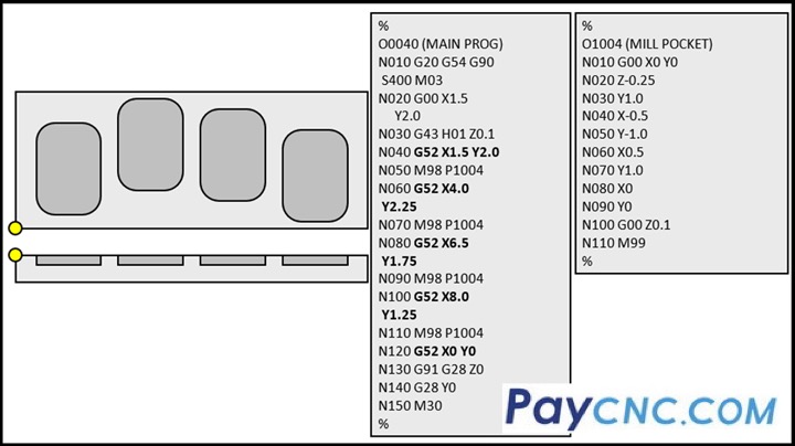
An example is shown in the figure. Although the drawing is not dimensioned, you should be able to follow along. In the main program, line N040, the local coordinate system command temporarily moves the origin from the lower left corner of the X-axis and Y-axis workpiece to the lower left corner of the leftmost cavity. Line N050 commands the execution of a subroutine to machine one cavity. Then, line N060 commands the coordinate system to move to the lower left corner of the second cavity. Line N070 again commands the subroutine to machine the second cavity. This is repeated two more times. Note that line N120 resets/cancels the local coordinate system. |
