Mazak CNC Machine Pitch Error Compensation Method
Applicable Models: VTC Series, QT Series
1. Entering the Pitch Compensation Interface:
• (1) Enter the machine diagnostic screen.
• (2) Enter the machine version screen.
• (3) Press the {1} version key, then the {2} page turn key, and input the password 1131.
• (4) Enter the compensation screen:
• (5) When performing pitch compensation on the MAZATROL system, the X axis is defined as 1, Y axis as 2, Z axis as 3, and the 4th axis as 4.
• P1 parameter is set to 80000, which means 80mm. For rotary axes, the standard setting is 10000, meaning 10 degrees.
• P2 parameter is set to 127. The same applies to the 4th axis.
• P3 parameter is set to 2. The same applies to the 4th axis.
• P4 and P5 are set to correspond to the X, Y, Z axes, and for the 4th axis, they are 0, 1, 2, 3 respectively. (Note: P4 and P5 settings must be consistent.)
• (6) When entering the compensation values, start from the 127th position and input the corresponding pitch compensation values. The spacing corresponds to the following:
• 127th position is always 0 value (for the 4th axis, it’s 0 degrees).
• 126th corresponds to a spacing of 40mm (for the 4th axis, 5 degrees).
• 125th corresponds to a spacing of 80mm (for the 4th axis, 10 degrees).
• 124th corresponds to a spacing of 120mm (for the 4th axis, 15 degrees).
• 123rd corresponds to a spacing of 160mm (for the 4th axis, 20 degrees)… and so on.
2. Calculation of Compensation Values:
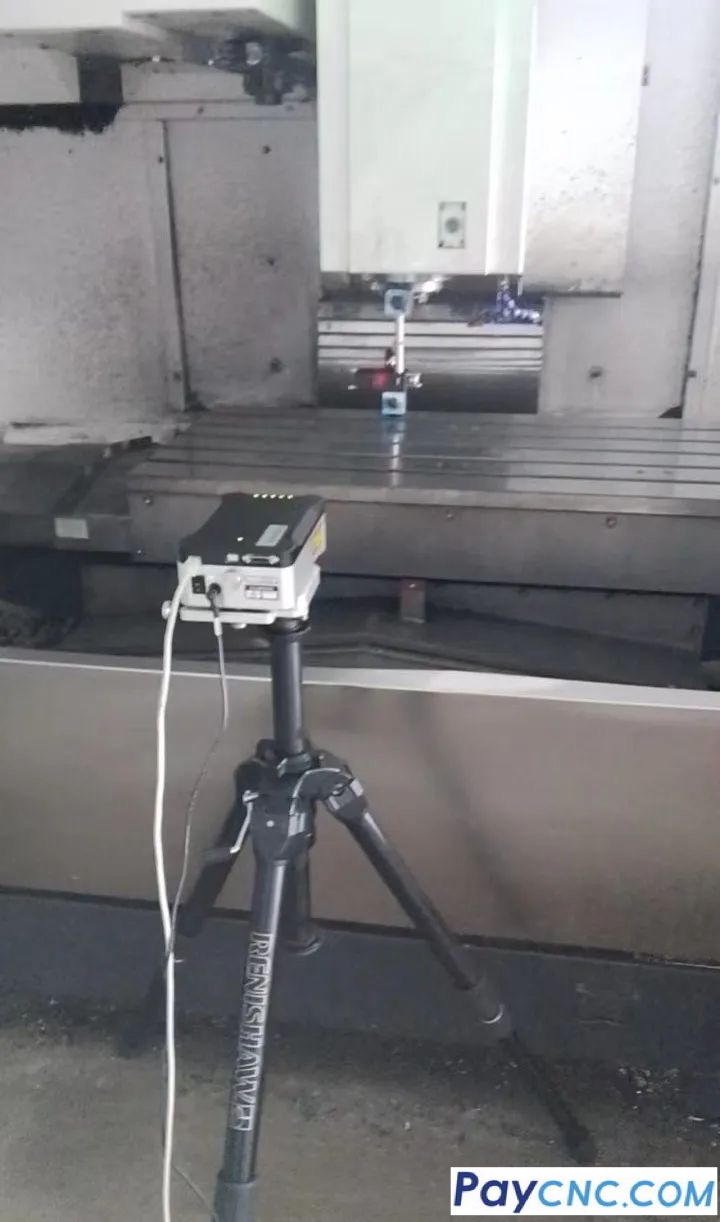
After sampling with a laser interferometer, a relative compensation method is used for calculation. Here’s an example:
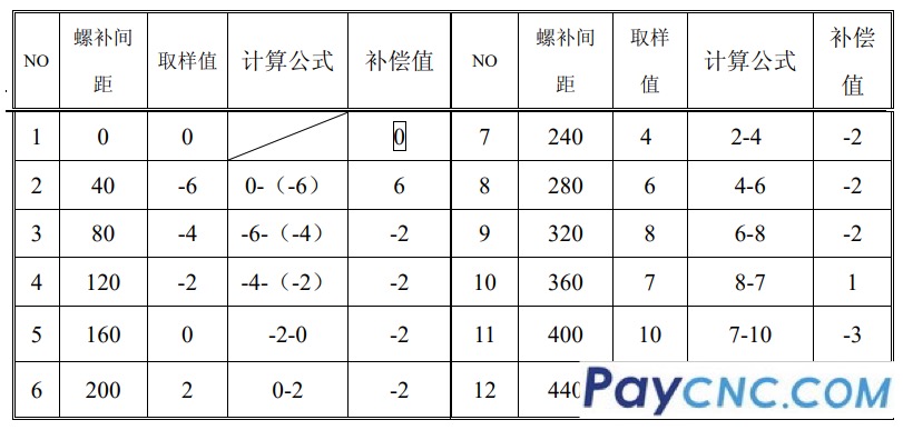
|
