FANUC | Implementation of the spindle multi-point orientation function
Spindle orientation control is also called spindle accurate stop control, that is, when the system receives the spindle orientation instruction (such as auxiliary function code M19), the spindle automatically rotates in the specified direction and speed. When the spindle rotation signal is detected, the spindle rotates to a fixed angle and stops accurately.
The function of spindle orientation control: It is mainly used for spindle positioning stop control during tool change in machining center, spindle positioning control during fine boring process, and C-axis positioning control of multi-functional lathe.
The spindle multi-point orientation function is also called "external setting of spindle orientation position". It is a standard function of 0i-D and 0i-C systems, and an optional function of 16i, 18i, and 21i systems. This function is needed when multiple orientation positions are required in a system application, for example, it is used to coordinate the system with multiple tool change systems and the positioning action before tool change. (Note: Multi-point spindle orientation is an optional function in 16i, 18i, and 21i systems. You can check whether this function is available through DNG1163#4.)
Parameter setting for multi-point spindle orientation
In terms of parameter setting, 0i-C, 16i/18i/21i series are similar, while 0i-D is different from the previous ones. The parameter settings and descriptions of 0i-C, 16i, 18i, and 21i are as follows:
Parameter
Setting
Function
3702#2
1
Use the external setting function of the spindle orientation position
4077
Spindle orientation stop position displacement
3117#1
1
DNG445 display function is valid (display spindle position data)
Parameter settings and descriptions of 0i-D:
Parameter
Setting
Function
3729#0
1
Use the external setting function of the spindle orientation position
8135#4
0
Use the spindle orientation function
4077
Spindle orientation stop position displacement
3117#1
1
DNG445 Display function is valid (display spindle position data)
Related signal signal description
Spindle
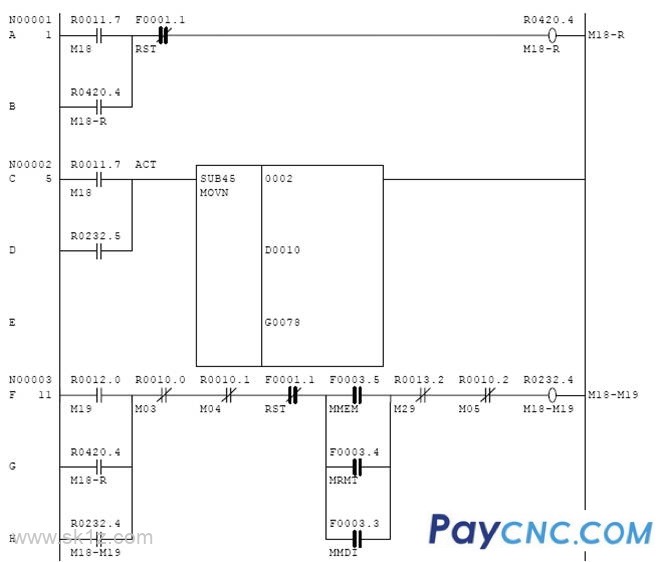
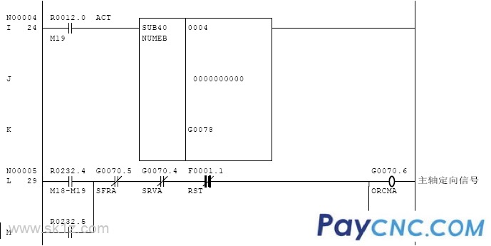
G70.6: Spindle orientation starts
F45.7: Spindle orientation ends
G78-G79: Spindle stop external offset
Use the external setting function of the spindle orientation position to pass its spindle offset angle to G78 and G79, and the value range is [0,4095]. The relationship between the value in G78 and G79 and the offset angle is a linear relationship between [0,4095] and [0o, 360o]. The spindle offset can be viewed in DNG445.
Note:
NO.4031 is the fixed offset of the spindle orientation. When the spindle orientation external setting is used, this parameter is invalid.
NO.4077 is the displacement of the spindle orientation stop position. Regardless of whether the spindle orientation position external setting function is used, this parameter is valid.
Whether to use external setting of spindle orientation
Spindle orientation position offset
No P4031+P4077
Yes P4077+G78~G79

 |
