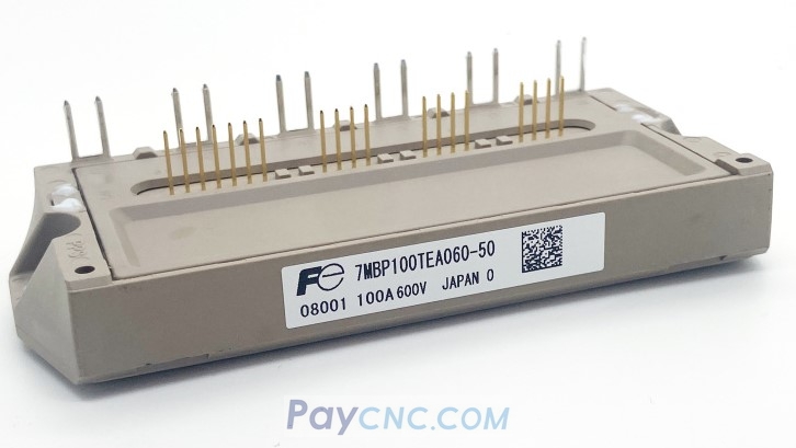
Methods for testing the quality of insulated gate bipolar transistors (IGBT) 1. Determine polarity
First, set the multimeter to the R×1KΩ position. When measuring with the multimeter, if the resistance between one pole and the other two poles is infinite, and the resistance between the pole and the other two poles is still infinite after swapping the test leads, then this pole is determined to be the gate (G). Measure the other two poles with the multimeter again. If the measured resistance is infinite, the measured resistance is smaller after swapping the test leads. In the case of measuring a smaller resistance, the red test lead is connected to the collector (C); the black test lead is connected to the emitter (E).
2. Determine quality
Set the multimeter to the R×10KΩ position, connect the black test lead to the collector (C) of the IGBT, and the red test lead to the emitter (E) of the IGBT. At this time, the pointer of the multimeter is at zero. Use your fingers to touch the gate (G) and the collector (C) at the same time. At this time, the IGBT is triggered to turn on, and the pointer of the multimeter swings to the direction of smaller resistance and can stop and indicate a certain position. Then use your fingers to touch the gate (G) and the emitter (E) at the same time. At this time, the IGBT is blocked and the pointer of the multimeter returns to zero. At this time, it can be judged that the IGBT is good.3. Any pointer multimeter can be used to detect IGBT. Note that when judging the quality of IGBT, the multimeter must be set to the R×10KΩ position, because the internal battery voltage of the multimeter below the R×1KΩ position is too low, and the IGBT cannot be turned on when testing the quality, and the quality of the IGBT cannot be judged. This method can also be used to detect the quality of power field effect transistors (P-MOSFET). 1. Static test 1. Test the rectifier circuit Find the P and N terminals of the DC power supply inside the inverter, adjust the multimeter to the resistance X10 position, connect the red test rod to P, and the black test rod to R, S, and T respectively. There should be a resistance of about tens of ohms and basically balanced. On the contrary, connect the black test rod to the P terminal and the red test rod to R, S, and T in turn. There is a resistance close to infinity. Connect the red test rod to the N terminal and repeat the above steps. The same results should be obtained. If the following results are obtained, it can be determined that the circuit has been abnormal. A. The resistance is unbalanced in three phases, which can indicate a rectifier bridge failure. B. When the red test rod is connected to the P terminal, the resistance is infinite, which can be determined that the rectifier bridge is faulty or the starting resistor is faulty. 2. Test the inverter circuit supply: Connect the red test rod to the P terminal and the black test rod to U, V, and W respectively. There should be a resistance of several tens of ohms, and the resistance of each phase is basically the same. The reverse phase should be infinite. Connect the black test rod to the N terminal and repeat the above steps to get the same result. Otherwise, the inverter module failure can be determined. 2. Dynamic test inverter After the static test result is normal, dynamic test can be carried out, that is, power on test machine. Before and after power on, you must pay attention to the following points: 1. Before powering on, you must confirm whether the input voltage is correct. Connecting a 380V power supply to a 220V inverter will cause the machine to explode (explode capacitors, varistors, modules, etc.). 2. Check whether the inverter ports are correctly connected and whether the connections are loose. Abnormal connections may sometimes cause the inverter to malfunction. In severe cases, the inverter may explode. 3. After power-on, check the fault display content and preliminarily determine the fault and cause. 4. If no fault is displayed, first check whether the parameters are abnormal, and after resetting the parameters, start the inverter under no-load (without connecting the motor) and test the U, V, and W three-phase output voltage values. If there is a phase loss or three-phase imbalance, the module or driver board is faulty. 5. When the output voltage is normal (no phase loss, three-phase balance), perform a load test. When testing, it is best to test at full load.
III. Fault diagnosis
1. Damage to the rectifier module
...
3. No display changes after power-on
This is usually caused by damage to the switching power supply or the soft charging circuit, resulting in no DC power in the DC circuit, such as damage to the starting resistor, or damage to the panel.
4. Overvoltage or undervoltage is displayed after power-on
This is usually caused by input phase loss, circuit aging and circuit board moisture. Find out its voltage detection circuit and detection point, and replace the damaged device.
5. Overcurrent or ground short circuit is displayed after power-on
This is usually caused by damage to the current detection circuit. Such as Hall elements, op amps, etc.
6. Overcurrent is displayed at startup
This is usually caused by damage to the drive circuit or inverter module.
7. The no-load output voltage is normal, but overload or overcurrent is displayed after load
This situation is usually caused by improper parameter settings or aging of the drive circuit and module damage. |
