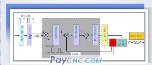
 In order to control the movement path of the tool, the CNC system must differentiate the continuous movement of the coordinate axis into the movement of a unit pulse. The actual movement corresponding to this unit pulse is called the minimum movement increment of the position control system or the command pulse equivalent, The command unit is usually 0.001mm.
After the coordinate axis enters position control, the CNC outputs command pulses according to the minimum movement increment, and the actual position is given a feedback pulse by the position detection device (such as pulse encoder, Pulse Coder) according to its resolution. The displacement amount corresponding to one feedback pulse is the detection pulse equivalent or detection unit.

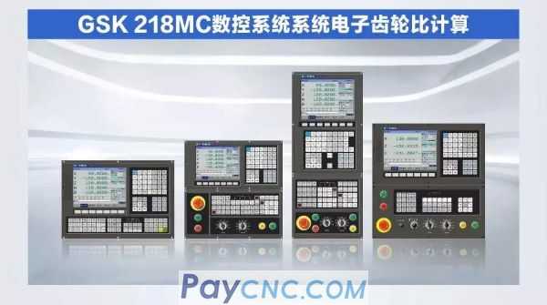
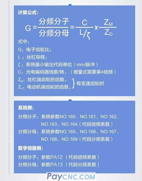
When the moving distance of the machine tool is inconsistent with the displacement distance displayed by the system coordinates, the system parameters P160~P164 and P165~P169 can be modified to adjust the electronic gear ratio to adapt to different mechanical transmission ratios. Set the position code pulse frequency multiplication (electronic gear). In the position control mode, through the setting of parameters, it can be easily matched with various pulse sources to achieve the user's ideal control resolution (ie corner/pulse). The system electronic gear ratio calculation of the 218MC system provides customers with a convenient, concise and intuitive operation interface. The following describes the system electronic gear ratio calculation in detail:
Calculation formula:

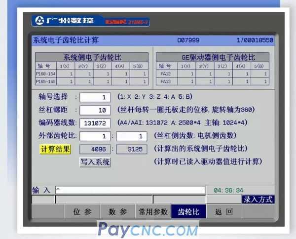
02 Use the system electronic gear ratio calculation interface
Select the corresponding axis number;
Set the lead screw corresponding to the axis; (the rotation axis is set to 360)
Enter the number of motor encoder lines; (A6: 8388608 A4: 131072)
When there is a transmission gear, enter the number of teeth of the screw end gear: the number of teeth of the motor end gear

Note: This interface is convenient for users to calculate the electronic gear ratio of the system. By default, the electronic gear ratio of the drive unit side needs to be kept at 1:1 (note that the bit parameter NO: 5#1 minimum moving unit), and the calculation result can be written into the system side. .
03 Conclusion
Through the above description, you can quickly understand the electronic gear ratio calculation of the system, and you can also use the electronic gear ratio calculation interface of the system. This interface effectively provides an intuitive and simple display interface, which makes the customer familiar with the operation and the convenience during the debugging process. Ensure the stability of processing and debugging.
|
 |
| Products Catalogue | Home | About Us | Retrofit | Download | News | Tech Support | Contact Us | |
|
|
|
