The CNC controller and multiple servo amplifiers or spindle amplifiers are connected through a high-speed serial servo bus (FSSB: Fanuc Serial ServoBus) with an optical cable, which can greatly reduce the cables required for electrical equipment of the machine tool and improve the reliability of servo operation Sex.
To use FSSB to control the feed axis, the following parameters need to be set.
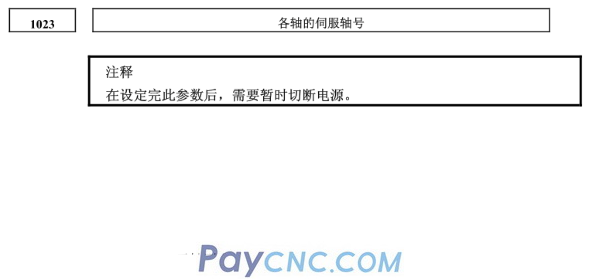
No.1023
No.2013#0
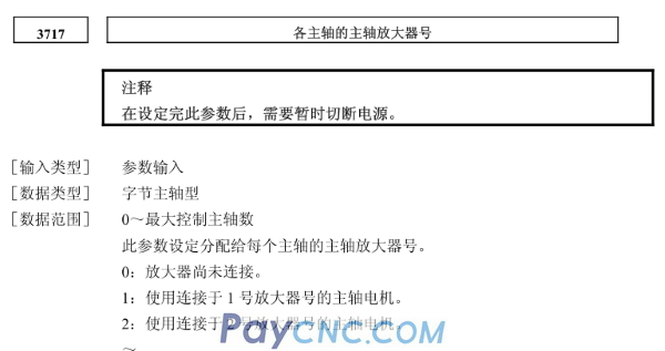
No.3717
No.11802#4
No.24000~24103
[Input type] parameter input
【Data Type】Byte shaft type
【Data range】0~Number of control axes
This parameter sets which control axis corresponds to the No. servo axis. Usually, the control axis number and servo axis number are set to the same value.
The control axis number indicates the arrangement number of axis type parameters and axis type machine tool signals.
For the axis for Cs contour control/spindle positioning, set-(spindle number) as the servo axis number.
When performing Cs contour control using the first spindle in the fourth control axis, set -1
In the case of a series control axis and an electronic gear box (hereinafter referred to as "EGB") control axis, it is necessary to set the 2 axes into one group, so please set it as shown below.
Tandem axis:
Set an odd number (1, 3, 5, 5, 7....... .) one of the servo axis numbers for the master axis. Set the value of the master axis plus 1 for the paired slave axis.
Remark: In the previous system of 0i-F series, the FSSB related parameters are different from the above, please refer to the related parameter manual.
There are three ways to set these parameters as follows.
1. Automatic setting
Use the FSSB setting screen to input the relationship between the axis and the amplifier to automatically calculate the axis setting, that is, automatically set the parameters (No.1023, No.2013#0, No.3717, No.11802#4, No.24000 ~24103).
2. Manual setting 1
The default axis settings are set by parameters No.1023 and No.3717. Therefore, there is no need to set parameters (No.2013#0, No.11802#4, No.24000~24103), and automatic setting is not performed. But it should be noted that some functions are not available.
3. Manual setting 2
Directly input all parameters manually (No.1023, No.2013#0, No.3717, No.11802#4, No.24000~24103).
2FSSB parameter setting method
Slave device
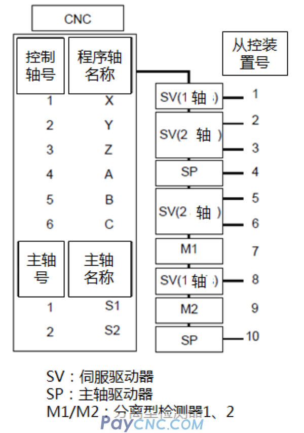
The system using FSSB connects CNC, servo amplifier, spindle amplifier and separate detector interface unit via optical cable. These amplifiers and separate detector interface units are called slave devices. The 2-axis amplifier consists of 2 slave devices, and the 3-axis amplifier consists of 3 slave devices. On the slave control device, assign numbers 1, 2, ... 10 (the slave control device number) to the FSSB in the order from the closest to the CNC.
Manual setting 1
When setting the following parameters, manual setting 1 is valid.
FMD(No.1902#0)=”0”
AES(No.1902#1)=”0”
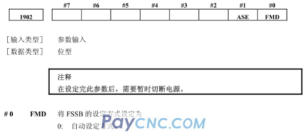 
In manual setting 1, when the power is turned on, the value set in parameter No.1023 and No.3717 is set as the slave control device number. That is, the servo axis whose parameter (No. 1023) is 1 is connected to the servo amplifier closest to the CNC, and the axis whose parameter (No. 1023) is 2 is connected to the amplifier next to the CNC; the parameter (No. 1023) is connected to the amplifier next to the CNC. The spindle motor whose value of 3717) is 1 is connected to the spindle amplifier closest to the CNC, and the axis whose parameter (No. 3717) value is 2 is connected to the amplifier next to the CNC.
The following functions and settings cannot be used in manual setting 1. Please set it automatically or manually2.
The separate detector interface unit cannot be used. Therefore, a separate position detector cannot be used.
It is not possible to skip the setting of the servo axis number of each axis in the parameter (No. 1023). For example, do not set the servo axis number 2
If it is set in any axis, the servo axis number 3 cannot be set in a certain axis.
The following servo functions cannot be used.
-Servo HRV3 control
-Tandem control
-Electronic Gear Box (EGB) (M Series)
Automatic setting
When the following parameter settings are made, the FSSB setting screen can be used for automatic setting.
FMD(No.1902#0)=”0”
Please follow the steps below to perform automatic setting based on the FSSB setting screen.
1 The amplifier setting screen displays the information of the servo amplifier, spindle amplifier, and pulse module in the order of the slave number.
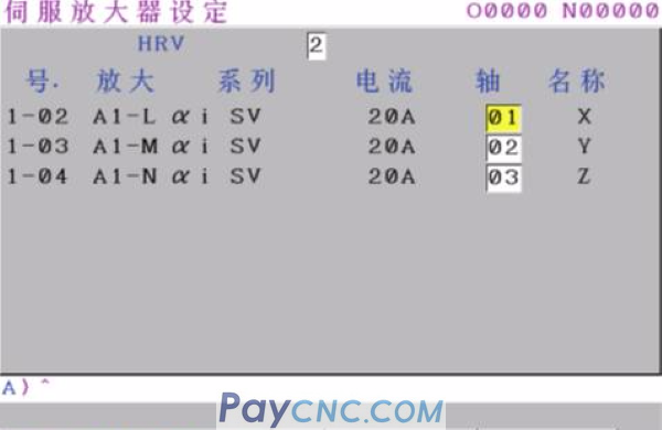
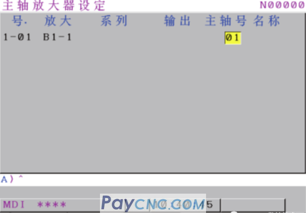
2 Set the axis control number and spindle number connected to each slave control device. At this time, the control axis name (except the pulse module) is displayed next to it. At the same time, the current loop control mode can be set.
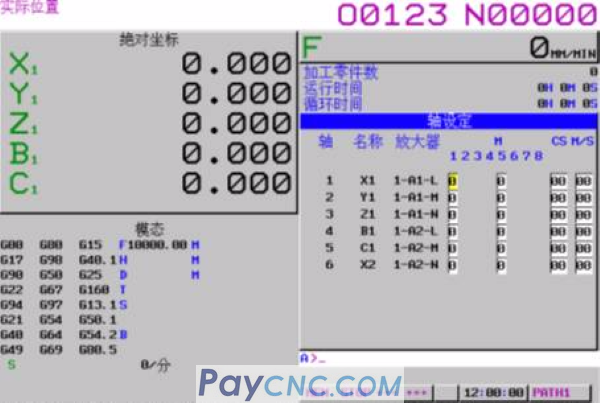
3 Select the axis setting screen, and set functional data such as the connector number of the pulse module for each control axis.
4 Press the soft key "Set" to make automatic settings. If there is a problem with the setting data, an alarm will occur. Please perform the correct setting again.
Perform automatic calculation through this operation and set parameters (No.1023, No.2013#0, No.3717, No.11802#4, No.24000~24103). In addition, the parameter AES (No.1902#1) indicating that the setting of each parameter has been completed is set to "1", and when the power is turned off/on, the axis setting is performed according to each parameter.
Manual setting 2
Set the parameter FMD (No.1902#0) to "1", or after the automatic setting is completed (after the parameter ASE (No.1902#1) becomes "1"), you can start the axis setting Manual setting of each parameter 2.
When performing manual setting 2, be sure to set the parameters (No.1023, No.2013#0, No.3717, No.11802#4, No.24000~24103).
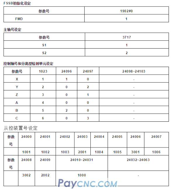
For details of FSSB setting parameters, please refer to the following FSSB data setting examples.
FSSB parameter setting case
For ease of understanding, this case describes how to set all parameters in manual setting 2 mode.
 |
 |
| Products Catalogue | Home | About Us | Retrofit | Download | News | Tech Support | Contact Us | |
|
|
|
