 Introduction: The assembly of the linear motor is carried out on the field machine tool. Unlike the permanent magnet motor, the zero adjustment of the encoder before the factory is completed uniformly on the workshop line, so the debugging technicians are required to understand and be able to perform straight line on the field machine tool. Motor zero operation.
01 Composition of linear motor
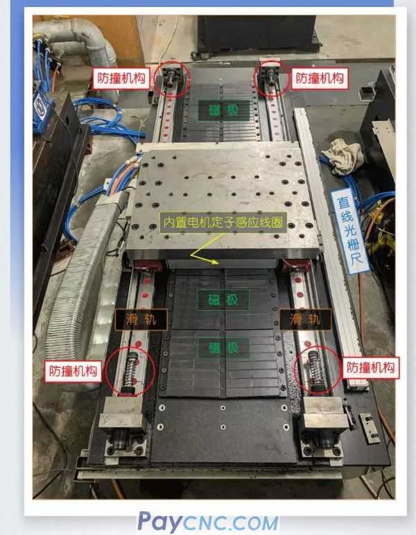
The working principle of a linear motor is similar to that of an AC permanent magnet synchronous motor. As shown in the figure, it is composed of a magnetic pole, a motor induction coil, a slide rail, a linear grating ruler, and a collision avoidance mechanism. Therefore, the debugging of the linear motor must first perform the zero adjustment operation of the linear motor encoder.
02 Safety reminder before zero adjustment
note!
Be sure to install the workbench accidental power-off protection and anti-collision protection mechanism at both ends of the machine shaft!
Make sure to turn on the cooling system before performing the zero adjustment operation or running the linear motor!
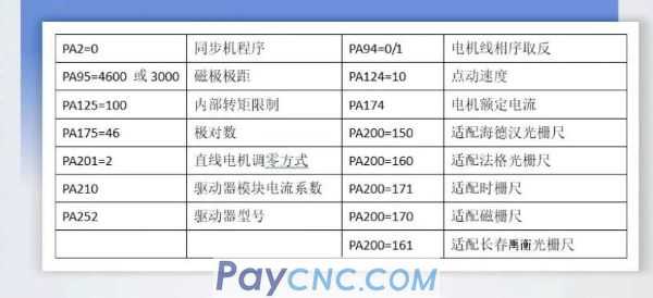
Before performing the zero adjustment operation, be sure to connect the motor temperature detection line to the driver or system and enable the temperature monitoring function! (The driving parameter PA182 = 0 is the shielding temperature detection, PA182 = 3 is the opening temperature detection.)
Before zeroing the vertical axis encoder, make sure that the holding brake is released! (There is a device equipped with a balance cylinder) It is necessary to adjust the pressure of the balance cylinder to ensure that the vertical shaft does not fall or rise when the brake is released!
During zero adjustment, make sure that no one is near the slide! Commissioning personnel can not be in the same direction as the slide's movement direction!
Be sure to monitor the Dp-l current during zero adjustment! The duration of the current being too large (showing that the current cannot exceed twice the rated current of the motor) should not exceed 8S, otherwise the power should be cut off immediately. At this time, pay attention to check whether the phase sequence of the motor line is wrong and whether the PA175 is wrong!
If there is only one direction (can't stop) during the zero adjustment process, pay attention to check whether PA175 and A201 are wrong! When Err6 or Err22 alarm appears, pay attention to check whether the phase sequence of PA94 and motor line is wrong!
Note that every time the zero adjustment is abnormal, you need to modify the parameters. After the parameters are saved, you must power off and then power on to operate the encoder zero adjustment again.
(After PA94 is modified and saved, it will take effect after power off).
03 Confirm the parameter before zero adjustment
The current linear motor driver is GR3000 (software version is V1.45, DSP is 28377 chip).
Related parameters:
04Encoder zero adjustment method
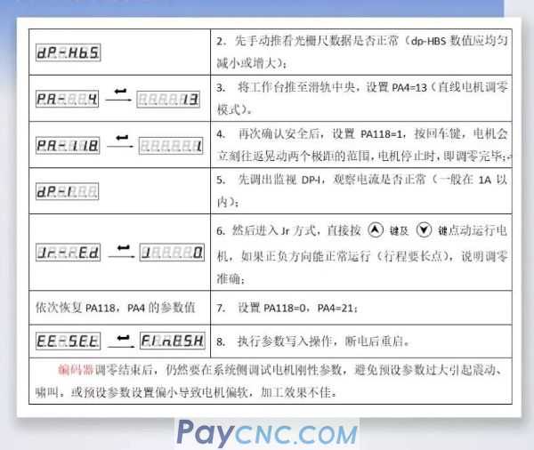
After confirming that the above parameters are correct, zero adjustment can be performed.
The preset rigid parameters: PA15 = 200, PA16 = 100, PA17 = 5000, PA18 = 5000, PA160 = 200, PA161 = 100, PA174 = (50% of motor rated current), this is personal experience value, because Strong rigidity is prone to E22.
 |
 |
| Products Catalogue | Home | About Us | Retrofit | Download | News | Tech Support | Contact Us | |
|
|
|
