The use of G41G42 radius compensation for CNC milling or machining center is nothing more than to facilitate programming and use on-site debugging. If you do not use G41 or G42, when machining parts on site, if the tool diameter needs to be changed, or the product has unqualified dimensions, you need to rewrite the program...
Therefore, it is necessary to share the compensation principle of these two instructions with you. You understand that G41G42 will also be very helpful for you to play software programming after processing.
Zou Jun I said that what is really useful is very simple, as simple as everything is divided into two states.
For example, up and down, left and right, east and west, male and female... These two states derive a rich and colorful world.
For example, the two forms of part features are either outer (shape) or inner (shape), which constitute the outer circle, inner hole, outer shape, inner cavity...
Similarly, tool radius compensation also has two compensation states, namely G41 left compensation and G42 right compensation.
1. Compensation is one left and one right, for one outside and one inside of the part, how to choose G41 and G42 during programming?
The essence is: looking along the direction of tool movement, if the tool radius is compensated to the left, it is G41, and the right is G42.
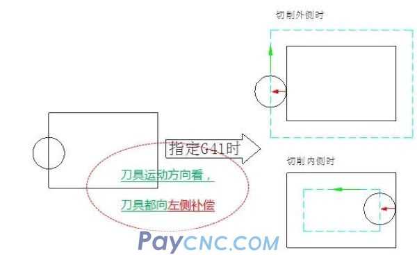
G41 is specified in the program, the operator inputs the tool radius value (positive value) in the machine tool radius compensation interface, and the tool will be compensated to the left when viewed along the direction of the tool movement.
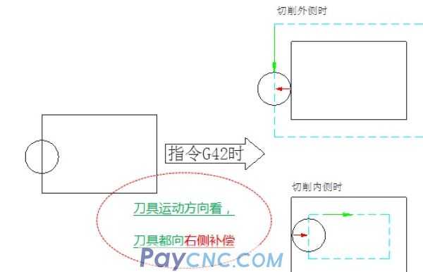
G42 is specified in the program, the operator inputs the tool radius value (positive value) in the machine tool radius compensation interface, and the tool will be compensated to the right when viewed along the tool movement direction.
2. The compensation process of CNC machine tools has 3 stages
1. Start compensation
2. Compensation status
3. Cancel compensation
1. Start the compensation phase:
We look at the above program:
N1 block: Compensation has not started yet, that is, the tool center is at X=0, Y=0 (not the tool edge)
N2 block: G0G41X20.Y10.D1 Start compensation, please note: X=20.Y=10. is the coordinate point of the edge of the tool (not the coordinate point of the tool center)
Because, from X=0, Y=0 to X=20. Y=10. The tool will gradually move to the left. (Because G41 is specified in the above program)
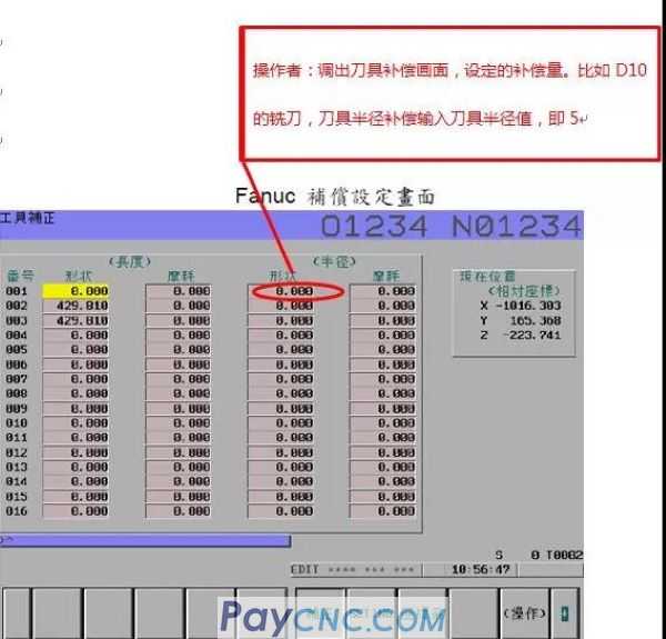
How much to move? The offset (positive value) is determined by the corresponding tool radius value entered by the operator in the machine tool radius compensation interface
For example, for the D10 milling cutter, input the corresponding tool radius value in the radius compensation interface, which is 5, then it will move 5mm like the left side. If you input 4, it will move 4mm.
Enter 0, then it will move 0mm (At this time, the tool center is at X20, Y10, which means there is no compensation)
Enter -5, then it will move -5mm to the left, in other words it moves 5mm to the right
Well, the above analysis and establishment of the radius compensation process, one is to specify the tool radius compensation command in the program, and the other is that the operator inputs the compensation value in the machine tool radius compensation interface.
After analyzing this, please note, we must pay attention to one sentence from my above:
From X=0, Y=0 to X=20. Y=10. The tool will gradually move to the left.
The two coordinate points from X=0, Y=0 to X=20. Y=10 are very important, that is to say, the X and Y values in the block before the radius compensation is established, and the X, Y in the radius compensation. value. At least one of the vertical distance between these two points is greater than the compensation amount in tool compensation.
Note: At the beginning of the compensation stage, it needs to be compensated in the G00 or G01 state (cannot be compensated under the G02 or G03 command, otherwise the machine will alarm)
2. Compensation stage
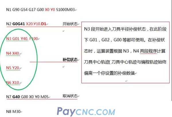
In the compensation stage, the machine tool system will pre-read the following two blocks (ie N3 and N4 blocks) to determine the vector direction of the compensation.
Therefore, it is recommended that the two blocks after G41 or G42 compensation cannot have Z values.
Proportion to this example:
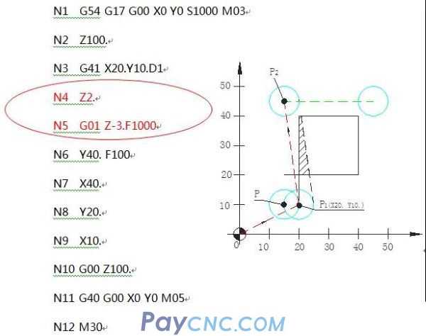 
When the radius compensation is established from the N3 section, the CNC system can only pre-read the following two blocks, and the N4 and N5 blocks are both Z-axis movement (the system cannot judge the vector direction of the next compensation, N3 block After execution, the tool path has changed, not the original point P, but point P1 (tool center point), and then move to the intersection point of P2 (gradual compensation), so the overcut is generated as shown in the figure above.
How to modify?
 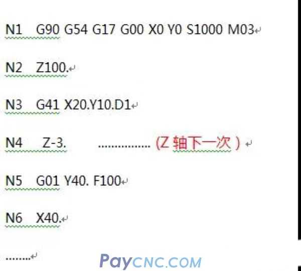 
3. Cancel compensation
The cancel tool radius compensation command is G40, and it must also be in the G00 or G01 state, and cannot be canceled under the G02 or G03 command.
The cancellation of radius compensation starts from the N7 block, (N7G40G00X0Y0)
From the end point of N6 block to X=0, Y=0 in N7 block is the end point, and the tool center returns to the (X=0, Y=0) point.
|
 |
| Products Catalogue | Home | About Us | Retrofit | Download | News | Tech Support | Contact Us | |
|
|
|
