Has the real system learned geometric tolerances? What knowledge does the geometric tolerance include? Let's take a look at the following picture first!
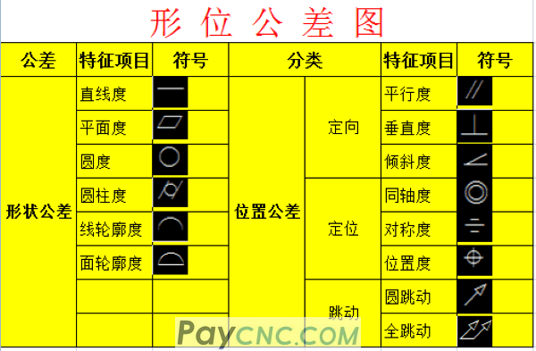
It can be seen from the above that there are 14 geometric tolerances in total. It can be divided into shape tolerance (6) and position tolerance (8), and the position tolerance can be subdivided into orientation tolerance, positioning tolerance, and runout tolerance. Today, the editor will share the knowledge of geometric tolerances with friends, all of which are dry goods!
Introduction to the basic concepts of geometric tolerances-basic terms
1. Basic terminology
1. Elements-refers to the points and surfaces that constitute the geometric feature points of the part.
2. Ideal elements-elements with geometric meaning
3. Actual elements-elements that actually exist on the part, usually replaced by measured elements
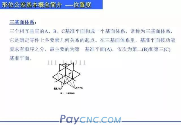
4. Reference element-an element used to determine the direction or (and) position of the measured element. Referred to as benchmark, it is the basis for confirming the geometric relationship between elements. Including datum point, datum line and datum plane.
5. Measured element-the element that gives the shape or (and) position tolerance
6. Central elements-points, lines, and areas that have a symmetrical relationship with the elements
7. Tolerance zone-limit the change area of actual shape element or actual position element. It is the area of a given maximum error, which is determined by its size, shape, direction and position.
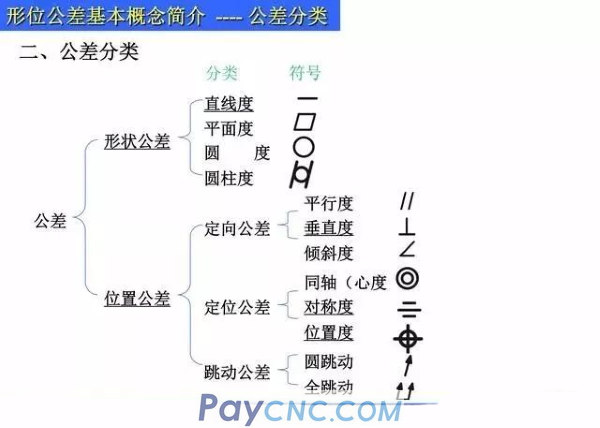 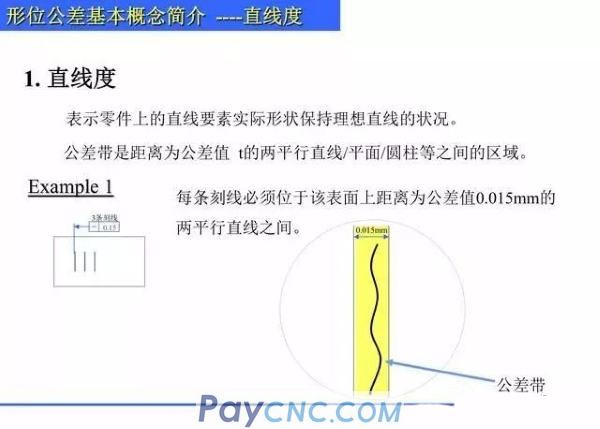 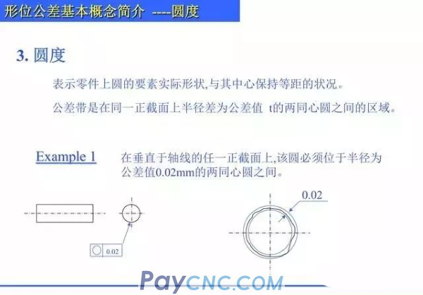 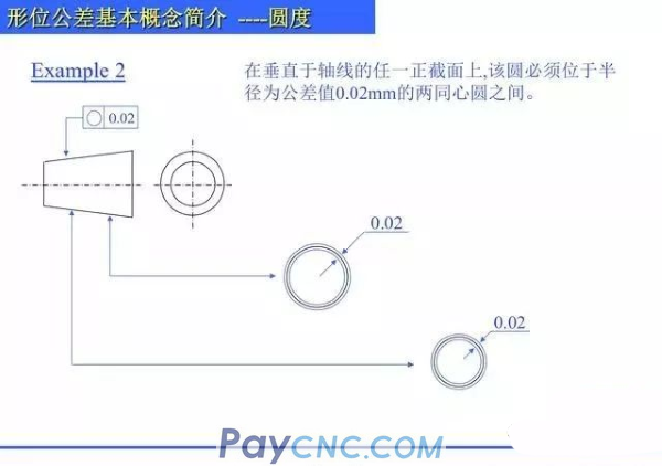
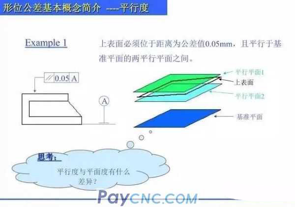
Parallelism
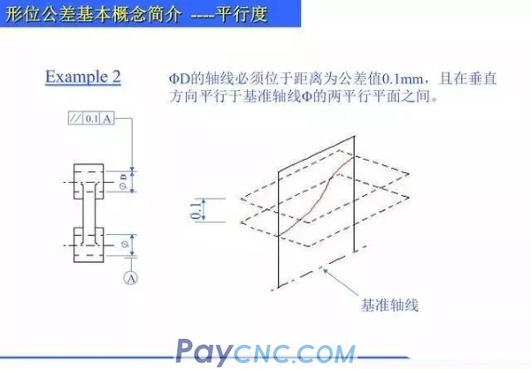
It indicates that the actual elements of the part being measured are kept equidistant from the reference. When a direction is given, the tolerance zone is the area between two parallel planes whose distance is the tolerance value t and parallel to the reference plane (or straight line or axis); when two directions perpendicular to each other are given, it is a normal section The size is the tolerance value t1Xt2, and the area within the quadrangular prism parallel to the reference axis.
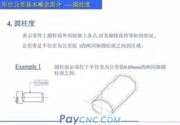 
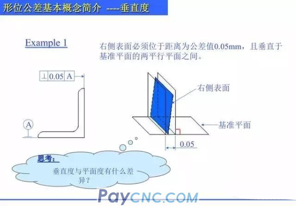
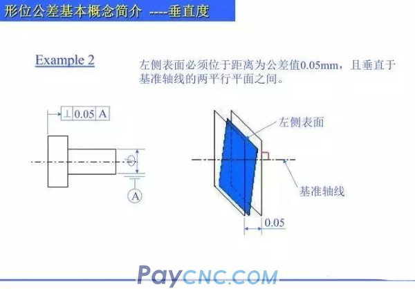
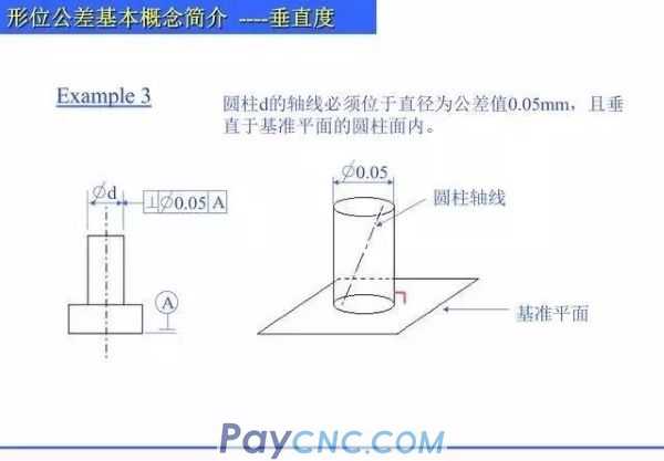
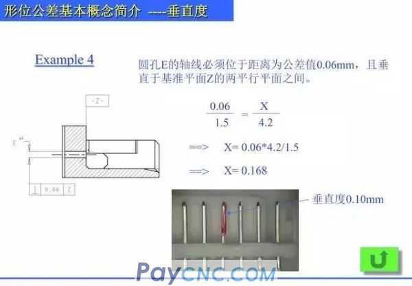
6. Verticality
Indicates that the measured element on the part maintains the correct 90 degree angle relative to the reference element. When a direction is given, the tolerance zone is the area between two parallel planes (or straight lines) whose distance is the tolerance value and perpendicular to the reference plane (or straight line, axis); when two mutually perpendicular directions are given , Is the area within the quadrangular prism whose normal cross-sectional dimension is the tolerance value t1Xt2 and is perpendicular to the reference axis.
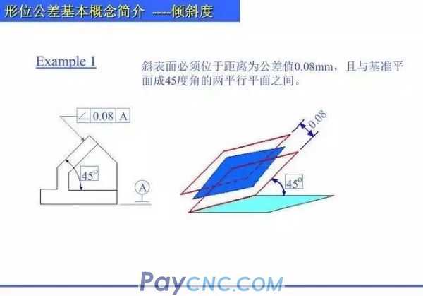
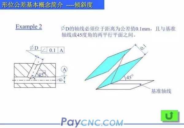
7. Tilt
It means that the relative direction of the two elements on the part maintains the correct condition at any given angle. In a given direction, the tolerance zone is the area between two parallel planes (or straight lines) whose distance is the tolerance value t and is at a theoretically correct angle to the reference plane (or straight line or axis).
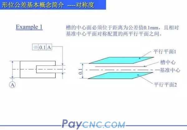
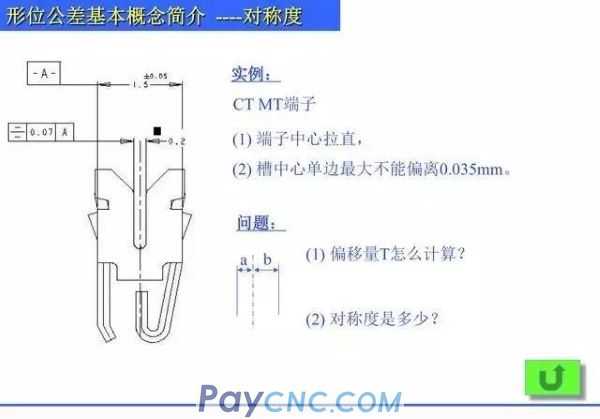
9. Symmetry
It means that the two symmetrical center elements on the part remain in the same plane. The tolerance zone is the area between two parallel planes (or straight lines) whose distance is the tolerance value t and is symmetrically arranged with respect to the reference center plane (or center line, axis). If two directions perpendicular to each other are given, it is the area within the quadrangular prism whose front section is the tolerance value t1Xt2.
 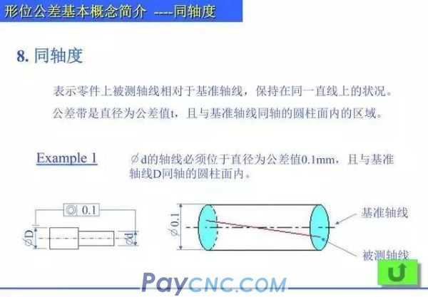
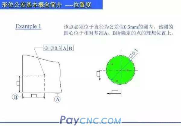
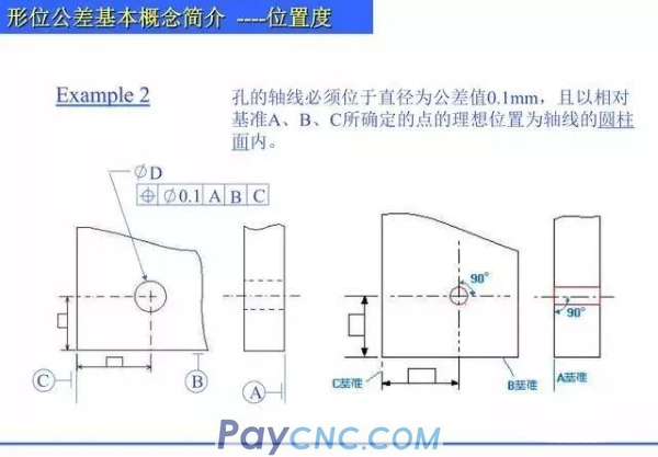
10. Location
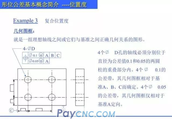
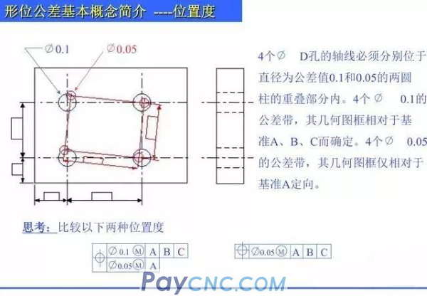
Indicate the accurate status of points, lines, areas and other elements on the part relative to their ideal positions.
Tolerance zone
1. The position of the point: the tolerance zone is the area within a circle or sphere whose diameter is the tolerance t and the ideal position of the point is the center.
2. The position of the line: when a direction is given, the tolerance zone is the area between two parallel planes (or straight lines) arranged symmetrically with the ideal position of the line as the center and the distance is the tolerance value; In the two vertical directions, it is the area within the quadrangular prism whose normal cross-section is tolerance t1Xt2 and the axis is the ideal position of the line.
3. The position of the surface: the tolerance zone is the area between two parallel planes whose distance is the tolerance value t and symmetrically arranged with the ideal position of the surface as the center.
11.Circle beat
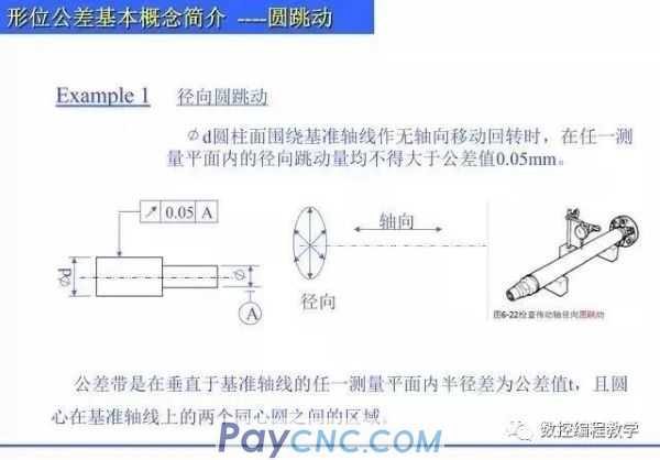
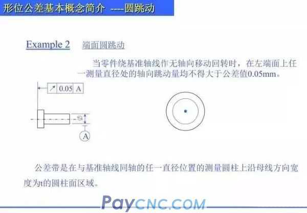
It means that the revolving surface on the part maintains a specified position relative to the reference axis within the defined measurement plane. (It refers to the maximum reading difference measured by the indicator in the designated direction when the actual surface to be measured rotates in the axial direction around the reference axis).
1. Radial circle runout
The tolerance zone is the area between two concentric circles on the reference axis where the radius difference in any measurement plane is the tolerance value t on the vertical reference axis.
2. End face round beating
The tolerance zone is a cylindrical surface area with a width t along the generatrix direction on a measuring cylinder at any diameter position coaxial with the reference axis.
12. Full beat
It means that when the part rotates continuously around the reference axis, the amount of jump along the entire measured surface is equal.
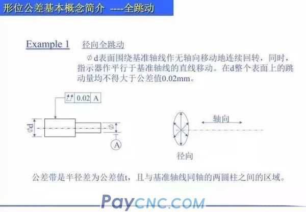
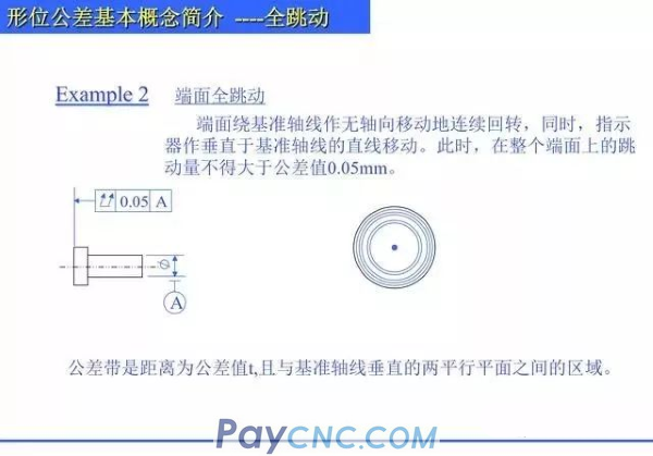
(It refers to the rotation of the measured actual surface around the reference axis without axis movement, while the indicator moves parallel or perpendicular to the reference axis, and the maximum reading difference measured by the indicator during the whole process)
1. Radial runout
The tolerance zone is the area between the two cylinders that the radius difference is the tolerance value and is coaxial with the reference axis.
2. Full end beating
The tolerance zone is the area between two parallel planes with a distance equal to the tolerance value t and perpendicular to the reference axis.
Summary of round beating and full beating
1. Radial circular runout is only measured on a certain cross section. The end face circular runout is only measured on a certain radius of the end face. The radial full runout is measured when the indicator is in contact with the measured cylindrical surface. In addition to the workpiece rotating around the reference axis, the indicator must be moved axially relative to the workpiece to measure the runout on the entire cylindrical surface. When measuring the end face full runout, the workpiece must rotate around the reference axis. It is also necessary to move the vertical axis of rotation relative to the workpiece so that the runout can be measured on the entire end face. For the same part, the total runout error value is always greater than the circle runout error value.
2. The total runout is equivalent to the combination of the runouts of all circles in the length direction.
  |
 |
| Products Catalogue | Home | About Us | Retrofit | Download | News | Tech Support | Contact Us | |
|
|
|
