Friends often ask me how to learn CNC macro programming?
Simplify complex things, streamline simple things
For example, when faced with a product picture, especially if it is complicated, it will be confused at first glance
In fact, there is nothing difficult in the world, as long as you are willing to resolve it.
Technicians are mainly doing this. They decompose product drawings into process drawings, and determine how to clamp each sequence, what tools and measuring tools to use, etc., to form a process file.
With this process file, it is much easier to organize the production and processing of parts, just follow the process.
This process can greatly reduce the probability of me making mistakes, allowing me to reduce the difficulty of doing things many times.
After knowing the power of proceduralization, I return to CNC programming, and I will teach you a two-step macro programming procedure.
Two steps teach you to write a macro program
The first step: set to determine the relationship between variables
Before writing the macro program, I don’t know where to start. Don’t worry about other things. To simplify the complicated things, start with the first step I told. Take out the pen and paper, set the variables, and find out the difference between the variables. The relationship between the variables is listed.
Step 2: Apply the macro case
Whether you can write a macro program depends on whether you have learned a macro case in your mind, and then apply the case. The layered milling that I shared before uses variables to control the depth of milling. When programming, you only need to write a layer of program to process the required depth. As shown below:
 
Having mastered the case of layered milling, now you have to write a similar program, set variables, etc. and then apply the case I provided you.
For example, the example of layered milling in the above figure:
The first step: set to determine the relationship between variables
After milling a circle, the tool will descend to a certain depth in the Z direction, and then after milling a circle, the tool will descend to a certain depth in the Z direction, and so on until the machining depth is reached.
If I use a variable to replace the milling depth, such as #1, set 1mm below each layer, then #1=#1-1 (make variable #1 self-calculate, and the value of #1 is reduced by 1 for each calculation), and start execution Assign a value of 0 to #1 as the starting point for calculation.
The first step is to set the determined variable relationship as follows:
#1=0
#1=#1-1
Step 2: Apply the macro case
The following is the main structure of layered milling
WHILE []DO1
#1=#1-1
...
...
Processing program
...
...
END1
In the first step, #1 is set to represent the milling depth. If the total depth of the part is -10, (the total depth can also be set as a variable) let #1 be compared with the total depth, namely #1LE-10
When the expression in the brackets is established, the blocks from WHILE to END1 are executed in sequence. It also realizes layered processing.
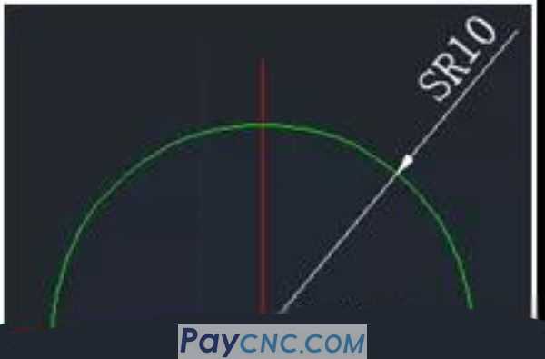
For example, in this case: Machining a spherical surface with a radius of SR10 on a digital milling machine. Select D12 milling cutter
The first step: set to determine the relationship between variables
G02 down milling is used for every milling circle, the tool is lowered to a certain depth and then milled one circle, and so on until the milling to the processing depth (that is, the contouring method in software programming)
If I use a variable to replace the milling depth, such as #1, set 0.1mm below each layer, then #1=#1+0.1 (let the variable #1 self-calculate, the value of #1 increases by 0.1 for each calculation)
#1=_____ Initial variable assignment
#1=#1+0.1 0.1 deep cut per layer
With the initial cutting depth #1 I set, I can calculate the decreasing value in the Z direction, set it to #3, and then calculate #3=10-#1 (as shown in the figure below). For example, the initial cutting depth is 1mm or # 1=1, then the value of #3 is 9.
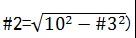
Know #3, then the X coordinate corresponding to the spherical Z coordinate satisfies the mathematical relationship #2²+#3²=10²
It can be calculated:
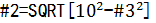
The square root of FANUC system is SQRT, so:
Step 2: Apply the macro case
Such as applying the layered milling case you have mastered
WHILE []DO1
#1=#1-1
...
...
Processing program
...
...
END1
Start programming
O0001
G40G49G80G90
G0X-18Y0 (under the knife point)
Z5M08
#1=0 (The initial cutting of the tool Z direction is 0.5mm)
WHILE[#1LE10]DO1(When the cutting depth is less than or equal to 10, execute the program between DO and END
#3=10-#1 (assign #3, the Z direction is decreasing)
#2=SQRT[100-#3*#3] (Calculate the value in the X direction)
#1=#1+0.1 (each layer is cut 0.1 deep)
G1Z-#1F100 (Infeed in Z direction)
G41G1X-#2F120D1 (X-direction positioning processing adopts left tool compensation)
G2I#2 (milling clockwise)
G1G40X-18Y0 (cancel tool compensation)
END1
G1Z5.
M30
 |
 |
| Products Catalogue | Home | About Us | Retrofit | Download | News | Tech Support | Contact Us | |
|
|
|