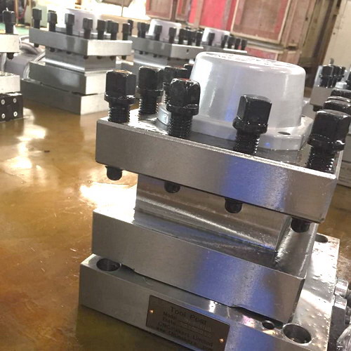
1) Mechanical reasons
The tool holder preload is too large. When a wrench is inserted into the end of the worm, it is not easy to rotate, but it can be rotated when force is applied. However, the tool holder still cannot start after the next clamping. When this phenomenon occurs, it can be determined that the reason why the tool holder cannot start is that the preload is too large, which can be eliminated by reducing the clamping current of the tool holder motor.
The internal machinery of the frame is stuck. When the worm is rotated from the end of the worm, it cannot be turned clockwise. The reason is that the machinery is stuck. First, check whether the back-receiving positioning pin of the clamping device is in the back-receiving ratchet groove. If it is, the back-receiving ratchet and the screw connection pin hole need to be rotated back an angle and re-drilled and connected; secondly, check whether the spindle nut is locked. If the nut is locked, it should be readjusted; thirdly, due to poor lubrication, the rotating parts are ground to death. At this time, they should be disassembled, the actual situation should be observed, and lubrication should be carried out.
2) Electrical reasons
The power supply is not connected and the motor does not rotate. Check whether the fuse is intact, whether the power switch is connected well, whether the switch position is correct, and whether the voltage value is within the specified range when the multimeter is used to measure the voltage. It can be eliminated by replacing the fuse, adjusting the switch position, and making the connection part in good contact. In addition, the reasons for the power failure can also be considered as the cable break between the tool holder and the controller, the internal wire break of the tool holder, the change of the position of the brush-type Hall element, and the normal disconnection of the forward input terminal and the reverse input terminal of the inverter.
If the manual tool change is normal and the machine control does not change the tool, the computer and tool holder controller leads, the computer I/O interface and the tool holder in place response signal should be checked. In the ladder diagram, the forward output signal Y0.0 and the reverse output signal Y0.1 are output at a low level when there is a signal input, resulting in no output of the corresponding relay. |
