How to set pitch error compensation on Mazak CNC machine?
Applicable models: VTC series, QT series
1. Entering the pitch compensation interface:
(1) Enter the machine tool diagnosis screen
(2) Enter the machine tool version screen;
(3) Press the {1} version key, {2} page key, and enter the password 1131;
(4) Enter the compensation screen:
(5) When performing pitch compensation, in the MAZATROL system, the X axis is defined as 1, the Y axis is defined as 2, the Z axis is defined as 3, and the 4 axis is defined as 4.
The standard setting of the P1 parameter is 80000; the meaning is: 80mm, the standard setting for the rotating axis is 10000, which means 10 degrees
The standard setting of the P2 parameter is 127; the same is true for the four axes
The standard setting of the P3 parameter is 2; the same is true for the four axes
P4 and P5 are set to correspond to the X axis, Y axis, and Z axis, and the four axes are 0, 1, 2, 3; (Note: P4 and P5 settings must be consistent)
(6) When inputting the compensation value, enter the corresponding screw compensation value starting from the 127th bit. The corresponding spacing relationship is that the 127th bit is always 0 (the four axes are 0 degrees), 126 corresponds to a spacing of 40mm (the four axes are 5 degrees), 125 corresponds to a spacing of 80 (the four axes are 10 degrees), 124 corresponds to a spacing of 120 (the four axes are 15 degrees), 123 corresponds to a spacing of 160 (the four axes are 20 degrees)... and so on;

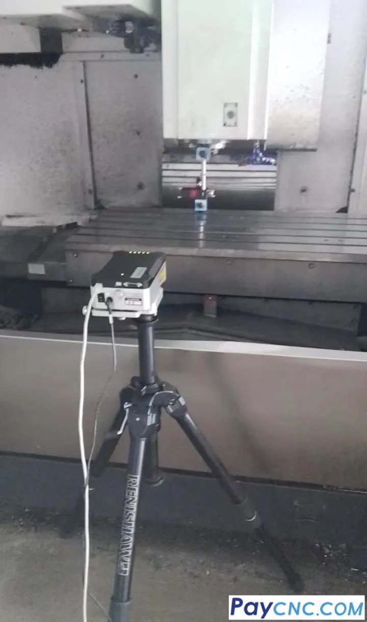
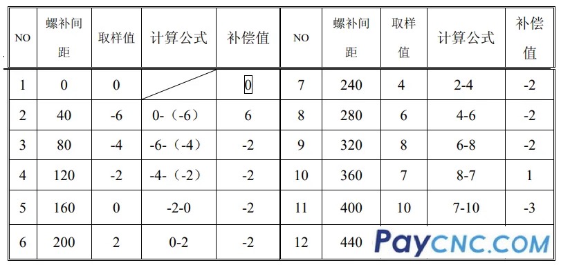
2. Calculation of screw compensation value: After the laser interferometer samples, the relative compensation method is used for calculation: For example:
 |
