IOR-44F IO Unit User Manual Installation

Specification
Chart 2-1. Note: The output signal of the IOR-44F model IO unit is active high, which is different from other models. ConnectionThe IO unit is connected to the 988TA series using the GSKLINK bus connection, and a GSKLINK connection line is introduced from the bus A and the bus B to the system by means of a loop connection.
Communication interface CN52485 interface, reserved 3.2 Spindle interface CN41和CN42
Power interface
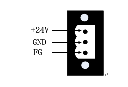 Figure 3-2 IO unit debugging The 988TA series CNC can be equipped with up to four IO units, and the address assigned to each IO unit can be assigned anywhere from X80 to X127 and Y80 to Y127.
parameter settings
『Modify permissions』:machine tool 『Ranges』: 0~4 『Factory default』: 0 Set the number of I/O units controlled by the system (up to 4)。
『Modify permissions』:machine tool 『Ranges』: 0,100~110 『Factory default』: 0 Set the system to control the logical ID number of I/O unit 1 (0 means that the I/O unit is not connected to GSKLink).
『Modify permissions』:machine tool 『Ranges』: 0,100~110 『Factory default』: 0 Set the logical ID number of the system control I/O unit 2 (0 means that the I/O unit is not connected to GSKLink)。
『Modify permissions』:machine tool 『Ranges』: 0,100~110 『Factory default』: 0 Set the logical ID number of the system control I/O unit 3 (0 means that the I/O unit is not connected to GSKLink)。
『Modify permissions』:machine tool 『Ranges』: 0,100~110 『Factory default』: 0 Set the logical ID number of the system control I/O unit 4 (0 means that the I/O unit is not connected to GSKLink)。
Address mappingThe parameters are set correctly. After the cable connection is completed, the system is powered on and the current operating authority is set to the machine manufacturer level.,按→GSKLink→1/0单元→1/0参数Soft key, enter the interface of Figure 4-1
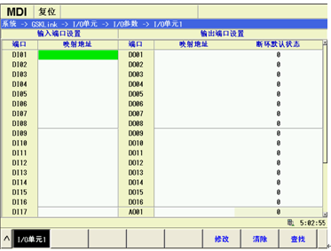 Pic 4-1 Note: When the IO unit is not assigned any address value, the mapped address is displayed as empty. When modifying the address of an IO unit, only eight input and output points of one byte (1 byte = 8 bits) can be set, and the address mapping of a certain bit cannot be modified individually.
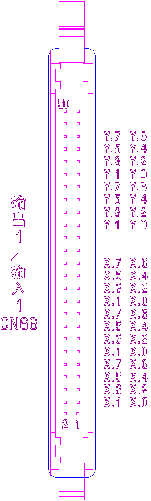
IOR-44F address mapping
table 4-1 Note: The address distribution of CN67 output 2/input 2 is the same as CN66 output 1/input 1. Adapt to the MCT-07 splitter.
4.2.2 988TA series standard ladder address settingAfter the GSKLINK bus communication is normal, press the 2 level machine tool manufacturer level authority GSKLink→Unit 1/0→1/0 parameter→ Soft key, through modify The button can set the mapping address corresponding to each byte. According to the configuration of the standard ladder diagram, set as shown in Figure 4-2.
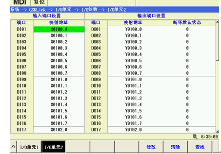
Figure 4-2 The system will list all the input and output points according to the current IO unit configuration. The input point is DI, the output point is DO, and the number of ports is allocated according to the number of input and output points. For example, the input points of the IO units that are adapted to the IOL-02T and IOR-44F are DI01 to DI48, and the output points are DO01 to DO32.
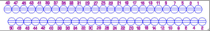
Adapter IOR-44FWhen the 988TA series CNC is equipped with the IO unit of the IOR-44F, the IO unit has 48 inputs and 32 outputs. The standard ladder configuration addresses in the system are X100 to X105 and Y100 to Y103. If you are using the system's standard ladder diagram, you must configure the IO unit according to the address defined by the ladder diagram. Since the IOR-44F is output by horn insertion, it is generally necessary to adapt a splitter like MCT07. The splitter is connected with the IO unit. The splitter is shown below.
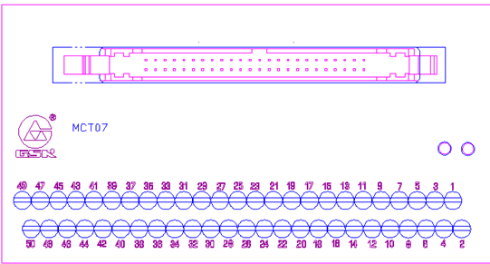 Figure 4-3 The address assignment is shown in the following table.
Table 4-2 Note: The address of another MCT07 and so on
Input signal connection There are two ways to input the external input signal: one uses a contact switch input, as shown in Figure 4-4.:
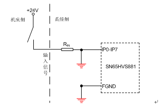 Figure 4-4 Contact switch input The other uses a non-contact switch (transistor) input, as shown in Figure 4-5, Figure 4-6.
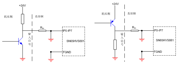 Figure 4-5 NPN type connection Figure 4-6 PNP type connection Output signal connectionOutput signal is highThe output signal is used to drive the relay and indicator on the electric line side of the machine tool or on the machine panel side. When the output is valid, the corresponding Y address output status is 1, the output interface potential is +24V; when the output is invalid, the corresponding Y address output status Is 0, The output interface behaves as a high impedance state. The circuit is shown in Figure 4-11.
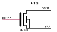 Figure 4-11 Internal circuit structure of the output signal Therefore, the output signal has two output states: +24V output or high impedance. Typical applications are as follows.
Ø Driving light emitting diode The output drives the LEDs and requires a resistor in series to limit the current flowing through the LEDs (typically about 10 mA). As shown in Figure 4-12 below
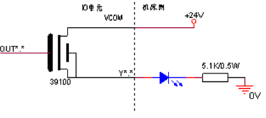 Figure 4-12 Ø Drive filament type indicator The output drive filament type indicator light needs to be connected with a preheating resistor to reduce the current impact during the conduction. The resistance of the preheating resistor is such that the indicator light is not bright, as shown in Figure 4-13.
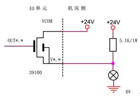 Figure 4-13 Ø Driving inductive loads (such as relays) The output drives the inductive load. In this case, a freewheeling diode needs to be connected near the coil to protect the output circuit and reduce interference. As shown in Figure 4-14
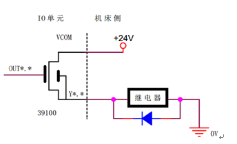 Figure4-13 Ø Driving inductive loads (such as relays) The output of the IO unit of the IOR-44F signal is active high, using the above connection method, the connection diagram is as shown 4-15
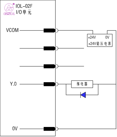 Figure 4-15 COM port connectionThe COM terminal in the IOL-44F output port should be connected to 24V, otherwise it will not output high level. | |||||||||||||||||||||||||||||||||||||||||||||||||||||||||||||||||||||||||||||||||||||||||||||||||||||||||||||||||||||||||||||||||||||||||||||||||||||||||||||||||||||||||||||||||||||||||||||||||||||||||||||||||||||||||||||||||
 |
| Products Catalogue | Home | About Us | Retrofit | Download | News | Tech Support | Contact Us | |
|
|
|